


Project: Example using a RTC to wake-up an Arduino Data Logger
This project is to give a practical example of using power save modes with Arduino's. It uses a Real Time Clock (RTC) to wake up an Arduino Data Logger. It write the temperature and humidity in a room to a micro SD card. It is optimized for saving power thus can run of a battery pack.
| Please put some money in the tip jar by clicking on the donate button to support me so I can continue creating contend like this. P.S. please donate more than $1 as PayPal takes minimum $0.30 per transaction |

This blog is an example project to explain how to use an Real Time Clock (RTC) module as a mechanism to wake up an Arduino we put to sleep. The code and explanation for putting an Arduino to sleep, and how to wake it up again can be found in this tutorial: A Guide To Putting Your Arduino To Sleep . For you to understand this project I strongly recommend you read this guide first as the code in this project is based upon the code explained in that tutorial.
Index
- The Project overview
- List of Materials needed for this project
- Downloads
- Connecting the Adafruit RTC 3231 breakout board
- The Code for the Adafruit 3231 RTC Breakout board
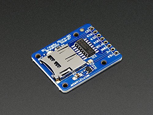
- Connecting the Adafruit Micro SD Breakout Board
- The code for the Adafruit Micro SD Breakout board
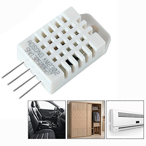
- Connecting the Humidity/ Temperature Sensor DHT11/DHT22
- The Code for the DHT11/DHT22
- Power/Current Consumption (mA)
The Project overview
The purpose of this project is to create a data logger that logs temperature/humidity data on an sd card. The data that gets logged has a date and time stamp. This project will run off a battery pack, thus we put the Arduino to sleep when no data is being logged.
In this project I am using the Adafruit DS3231 RTC breakout board. I used this particular one because of it has a SQW pin, and it uses two Analog pins for communication. In most projects the Analog pins are not used so the RTC does not take up valuable digital pins.
The other feature of this RTC is that you can set alarms that get activated without the need to communicate with the Arduino board (Your Arduino can be asleep and the alarm will still fire). When the alarm fires it pulls the SQW pin to low. We use that action to fire the Interrupt attached to digital pin 2 to wake up an sleeping Arduino, as explained in the turorial (A Guide To Putting Your Arduino To Sleep).
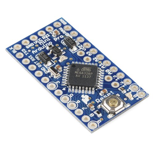
Arduino Pro Mini side view to show how to solder in pin A4 and A5
We use the DHT11/22 sensor to read the temperature and humidity of a specific room, and the Adafruit micro SD breakout board to write the data to an SD card. The Arduino used is the Arduino Pro Mini. When soldering the header pins also put header pins pointing upwards in the A4 and A5 holes. We will be using these to communicate with the RTC breakout board
List of Materials needed for this project
Note: This is the first project where I will be using links to Amazon products to list what products are needed. I do this just to recover the costs of the components I use. I don't sell any of these items, but will receive a very small commission. Please consider using these links to buy your products to support me creating these projects/tutorials.

Downloads
The next list has all items needed to be downloaded for this project. It is recomended to do this before you continue onwards to download all files.
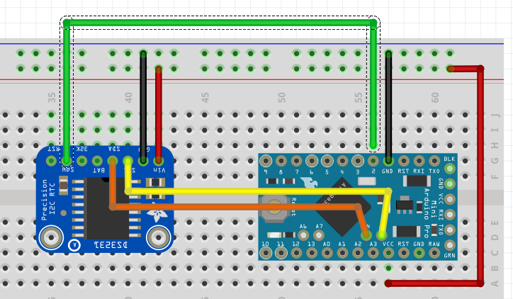
Connecting the Adafruit RTC 3231 breakout board
Lets look at how to connect the RTC to your Arduino Pro Mini:

| DS3231 RTC PINS | Arduino/Breadboard Pins |
| 5V | breadboard 5V |
| GND | breadboard GND |
| SCL | Arduino A5 |
| SDA | Arduino A4 |
| SQW | Arduino D2 |

| SD Breakout PINS | Arduino/Breadboard Pins |
| 5V | breadboard 5V |
| GND | breadboard GND |
| CLK | Arduino D13 |
| DO | Arduino D12 |
| DI | Arduino D11 |
| CS | Arduino D10 |
This image shows you what it would look like on your breadboard
The code for the Adafruit Micro SD Breakout board
The code for this breakout is easy to understand and strait forward. First we load the libraries

The libraries used are part of the Arduino IDE so no need to download anything special here. Next we declare the global variables needed for this board.

First we declare the File name object named myFile, than we declare a constant int (chipSelect). This variable sets the digital pin needed for the Adafruit breakout board. Don't change it, Adafruit wants it to be that pin so we are stuck with it like this.
The actual writing to and reading from a file is done in a function called writeData().
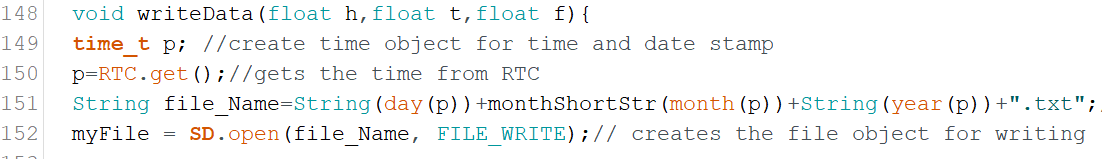
If you remember that this whole sketch is to log temperature and humidity data onto an sd memory card. In this function we do the actual writing. We send this function 3 arguments; float h (humidity), float t (temperature in Celsius), and float f (temperature in Fahrenheit ).
On line 149 we declare another time variable named p, and get the current date and time from the RTC on line 150. We do this for 2 reasons. Reason one is to create a filename that is today's date. This way it is easy to see when data was logged, and reason two is that we use the current time as a time stamp to know exactly when the data was logged.
On line 151 we create a string called file_Name. The string contains today's date. We use the time/date variable to do so. On line 152 we use the string to open, or create a file with the file_Name variable content as name with the SD.open() function. Lets look a bit closer at the syntax of this function.
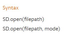
The filepath is the path to the file including the filename. The mode is either FILE_READ to read from a file, or FILE_WRITE to append to a file. If you use the FILE_WRITE with a filename that does not exist it will create the file name. If you use the SD.open(filepath) it will automatically assume you want to read from the file. If you want to see all option click on the following link; https://www.arduino.cc/en/Reference/SDopen
The SD.open() action gets stored in the myfile object created in the declaration section. Now we have the file open and are ready to write to it.
Click to Enlarge
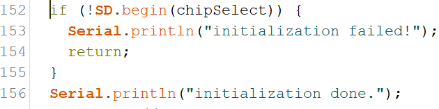
The if(myFile) statement checks if the file exist and is in the correct format. If this statement returns a false it will print an error message to the Serial Monitor. The most common reason for this is that the sd card is not formatted correctly or not in its socket, or you used a filename that contains characters that are not allowed.
Note: The Adafruit breakout board requires a specific format. For more information on this go to the following link: https://learn.adafruit.com/adafruit-micro-sd-breakout-board-card-tutorial/formatting-notes
On line 158 we actually write to the file. We use the same format used to print a line to the serial monitor, but instead of using Serial, we use the file object myFile. After we wrote to the file we close it with the myFile.close(); line. It is very important that we close the file after reading or writing to it. If the file is not closed correctly it will be corrupted and you won't be able to write to or open that file again.
Connecting the Humidity/ Temperature Sensor DHT11/DHT22
The pinout of this sensor is done with the sensor front grid facing you:
| DHT11/22 | Arduino/Breadboard Pins |
| 5V | breadboard 5V |
| Data out | Arduino D4 |
| GND | breadboard GND |
| GND | breadboard GND |
The image shows all components on the breadboard.
The Code for the DHT11/DHT22
In my sketch you will see the code for the DHT11 as I have this sensor in my collection of sensors, but if I had to use this project in a real world scenario I would use the DHT22 as it has greater precision.
We are using the Adafruit library. You are right this project is definitely Adafruit centric. No I am not getting paid by Adafruit, but if LadyAda is listening I can always use some cash. But enough with the useless banter as you are here to learn something. Lets look at the declaration section for this sensor;
First we load the library

Next we are creating the object to communicate to the sensor and some global variables we need to create the object;

On line 27 we declare the variable that tells the sensor what digital pin we communicate with. We use digital pin 4.
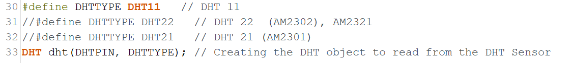
As I explained I am using the DHT11, but if you use the DHT22 comment out line 30 and un-comment line 31. Next we create the dht object on line33. We use the DHTTYPE variable to let the object know what sensor we using, and the DHTPIN variable to let it know what pin to communicate with.
In the setup() function we use the following statement to start communication with the sensor;

The actual reading from the sensor is done in function temp_Humi(). This function is called from line 107 from the Going_To_Sleep() function.
Click To Enlarge
In this function we read the Humidity % with the dht.readHumidity() function, and the temperature both in Celsius dht.readTemperature() and Fahrenheit dht.readTemperature(true). We store these in float variables (h for humidity,t for temperature in Celsius, and f for temperature in Fahrenheit). We take these float values and pass them to the writeData() function where they are written to the SD card.
Power/Current Consumption (mA)
After we tested the code and see how the project runs using the FTDI cable it is time to connect it to an external power supply and a multimeter. We do this to measure how much current we draw. If you are not sure how to do this, check out my tutorial: How to measure power consumption and why should to do it.
After hooking up the project with an external power supply and multimeter we see it consumes 24-28mA when awake and a small 100th of a second spike of 100mA as we write to the SD card. When it is sleeping it only uses 10mA. We can actually save a couple of more milliAmps out of the circuit if we were able to turn the power off on the SD breakout board. Actually we save almost 7mA ending up with only a use of 3mA when it is asleep.
We do this by using an NPN transistor as a switch to turn the power off on the SD breakout board when the Arduino is asleep.
Note: When you put the Arduino to sleep all the components are still drawing a base current. If we can turn off the power on these components we lower the current/power consumption even more.
This a bit advanced so I won't go in to details how an NPN Transistor works, but I will explain how to implement it. Checkout the image below to see what the diagram looks like.
Hardware alteration
Using the 2N2222/MPS2222A transistor, we connect a 1K resistor to the middle leg of the transistor, connect the other end of the resistor to D9 on the Arduino. By putting pin D9 high we turn the switch on, and by putting pin D9 low we turn the switch Off. Next we connect the right leg of the transistor (with the flat part facing you) to the 5V on the bread board and connect the left leg to the 5V in on the SD breakout board.
Note: You might ask why don't we do this for all the components to save even more. Some components need to have power as they need to do things while the Arduino sleep e.g. the RTC needs to wake up the Arduino, and some components take time to start working when power is applied to them e.g. the Humidity/Temperature Sensor. This you find out through trial and error.
Code alterations:
You can download the completed power saver version of the sketch from here

On line 39 we add the following line to declare the pin we use to turn the power on and off on the SD breakout board. Next we make digital pin 9 an out put pin and turn it high with the following code
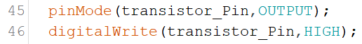
We add these lines in the setup() function on line 45 and 46. Then in the Going_To_Sleep() function we pull digital pin to low to turn of the power to the SD breakout board just before we put the Arduino asleep with this line of code. We put it on line 101

After the Arduino is woken up we add a line of code that will pull pin 9 back to high on line 109 before we call the temp_Humi() function.

Finally we have to reinitialize the SD breakout because we powered it down. We do this in the writeData() function. We do this before we declare the time object with these lines of code;
Making these alterations to your project make it even more energy efficient.
In Closing
This is a practical application that shows when putting your Arduino to sleep really can have practical applications. This project can run on 4 C cell batteries for approximately 3 to 4 weeks. If you run it without the sleep mode you only get 4 to 7 days out of it.
If you like this project and would like to see more of the same type, please subscribe to my newsletter using the form below or like and follow my Facebook page. This way you get notified when a new post is available. If you have questions or suggestions please email at akurk@thearduinomakerman.info me or leave it in the comments below. Have a great day and see you next time.

Tutorial:A guide to putting your Arduino to sleep
Tutorial:A guide to putting your Arduino to sleep
If you need to run your Arduino of a battery pack, you need to find a way to reduce it's power consumption. One of the the best ways to do this is putting your Arduino to sleep when it is not performing any tasks. This tutorial is a great place to start on learning how to put your Arduino to sleep.
| Please put some money in the tip jar by clicking on the donate button to support me so I can continue creating contend like this. P.S. please donate more than $1 as PayPal takes minimum $0.30 per transaction |

Sometimes we are in a situation that requires us to put an Arduino in a place where plugging it in to the power grid is not an option. This happens often when we try to log information in a remote site, or only need to have your Arduino active at a specific interval/action.
In these cases putting your Arduino to sleep is the perfect thing to do. Their attention is only required for a short amount of time e.g. log data in a specific interval, or put out an alert when a predetermined event happens. In this tutorial we are going to experiment with putting your Arduino to sleep and see how to turn your Arduino back on.
This tutorial familiarizes you with the concept and has a small exercise to see what it takes to put an Arduino to sleep. In the next couple of blog posts (in 2 weeks or so) I will show post a couple a projects that will show you how to wake your Arduino using a sensor, or a Real Time Clock module (RTC).
MATERIALS NEEDED IN THIS TUTORIAL


What board to use?
In this tutorial we will be using the Arduino Uno just because it is an easier board to prototype on. In a real live project I would use an Arduino Pro Mini for this. The Arduino Uno and the Arduino Pro Mini have very similar characteristics, the Arduino pro mini has a lot less hardware to power (e.g. the USB portion, extra leds, and some other stuff) thus using a lot less power. This is the reason why the Arduino Pro mini is a better choice.
To give an example a Uno uses between 30-40 mA when awake and about 19 mA when asleep. The Pro Mini uses 25mA when awake and 0.57 mA when asleep. As every mA matters when hooking it up to a battery you can see that there is no contest and the Arduino Pro Mini is the winner.
Note: As a beginner Maker the Arduino Pro Mini might be a bit intimidating, but there is no reason for it. Yes you need to solder the headers onto the board, and you need a FTDI cable to upload your sketch, but other than that there are no major differences.
Sleep mode
When you look at the documentation of the ATmega328p (click this link for a copy of this document) processor used for both Arduino Uno and the Arduino Pro mini you notice there are many different sleep modes available. But in a real world scenario there is really only one mode that is useful; The Power down mode (SLEEP_MODE_PWR_DOWN).
When you put your Arduino to sleep it turns off all unnecessary components, reducing the power consumption of the MCU (Microcontroller Unit). In this mode the only way you can wake it up is the use of an external influence (e.g. we give it a nudge to wake up). We will examine how to do this a bit later in this tutorial.
Interrupts
Before we go into the code to put an Arduino to sleep we need to understand the interrupt concept. The best way to describe it is ; You are working on something you really need to concentrate on. You wear headphones blasting your music loud to drown out your surrowndings . You are so concentrated on this that the outside world is lost to you. The only way to get your attention is by giving you a nudge. After you receive this nudge you pay attention to what the interruption is about, and after dealing with it you put the music back on and continue with your task.
Note: I am not going to go to deep into what interrupts are good for, but if you want to learn more about this concept check out my tutorial (Using Interrupts to improve the functionality of your project) on this topic
Most true Arduino’s have a couple of pins that do just that. The Uno and the Pro Mini have 2 pins (d2 and d3) that have the capability to interrupt what the Arduino is doing. With this we can nudge the Arduino back to a waking state.
Putting your Arduino To Sleep
You can download the code for this section for here.
Let’s look at the code for this section
Image_1 click to enlarge
Image 1 contains the code snippet that loads the library that contains everything we need to put your Arduino to sleep, We also declare the variable interruptPin for digital pin 2. We will later use this for making pin 2 an input pin. Next we will look at the Setup() function.

Image_2 Click To Enlarge
Image 2 has the code for the Setup() function. It is all straight forward. We declare digital pin 13 as an output pin (LED_BUILTIN is a build in variable for digital pin 13 where an onboard led is connected to). We are using the LED as an indecator for when the Arduino is asleep (when LED is on Arduino is awake, when off the Arduino is asleep).
On line 18 we set digital pin 2 as an input pin. You notice we use INPUT_PULLUP instead of INPUT. By doing this we use the build-in pull-up resistor to prevent the pin from flopping between HIGH and LOW when nothing is attached to it (same thing you would do with a button).
Next we are going to the main loop() function;
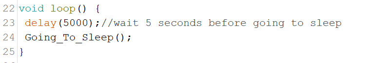
Image_3
On line 23 we put in a delay of 5 seconds before we call the Going_To_Sleep() function on line 24. This is just so you can see that the onboard LED is on to show your Arduino is awake, and the moment we call this the Going_To_Sleep() function the LED goes off to indecate the Arduino is asleep.
Next lets look at the Going_To_Sleep() function itself;
Image_4 Click To Enlagre
On line 28 we call the sleep_enable() function which is part of the avr/sleep.h library. It enables us to put the Arduino to sleep, without calling it we can't put the Arduino to sleep. On line 29 we attach an interrupt to pin 2 as I explained in the Interrupt section.
Syntax
attachInterrupt (interrupt, ISR, mode);
As you notice we use a 0 to indicate that we are using pin 2. This is because the Arduino Uno/Pro Mini have 2 interrupts. Interrupt 0 is connected to digital pin 2, and Interrupt 1 is connected to digital pin 2. The ISR is the function name that is called when the interrupt is called. In our case it is called wakeUp. The mode is what needs to happen to the digital pin to call the interrupt. In our case the pin needs to be pulled LOW (to GND).
On line 30 we set the set of sleep mode we want. In our case it goes and shuts down everything it can. On line 31 we turn off the LED, and on line 32 we wait a second to give the board the time to turn the led off. Next we actually put the Arduino to sleep with the sleep_cpu() function.
The code halts here until the interrupt is called. After waking up the Arduino will first execute the code in the wakeUp() function and then will continue with line 34 printing the wakeup message on the serial monitor, and on line 35 turning the LED back on.
Image_5
In the wakeUp() function we print a line to the serial monitor to let you now the interrupt has been called. The next two lines are very important to make sure we do not get an unintentional loop where the sketch can get stuck, and making your project fail.
On line 40 we disable the sleep function, and on line 41 we detach the interrupt from pin 2. As I said we do this to prevent a possible endless loop situation.
Exercise 1
Step 1)
Now it is time to upload the sketch. But before doing that put a jumper wire in d2. Just leave it unplugged on the other end for now. Load your sketch and wait 5 seconds for the LED to turn off and the Arduino to go to sleep.
Step 2)
After the LED turns off insert the other end of the jumper wire in a GND pin on your Arduino Uno. This will pull pin 2 LOW triggering the interrupt, thus awaking the sleeping Arduino. After the LED comes back on you can remove the jumper wire out of GND and 5 seconds later the Arduino goes back to sleep.
IN CLOSING
Now you know the principles of what it takes to put your Arduino to sleep. As you see it is a very simple process. Finding a good mechanism to control this project is sometimes a bid more problematic. For this reason I will post a couple example projects on how to wake up an Arduino using a sencor (e.g. motion sensor), and a Real Time Clock module (RTC) that will be designed so you can use them and integrate that into your own project.
If you like this tutorial and would like to see more of the same type, please subscribe to my newsletter using the form below or like my Facebook page. This way you get notified when a new post is available. If you have questions or suggestions please email me or leave it in the comments below. Have a great day and see you next time.