


Project: IOT Christmas Lights Display
A couple of year’s back I bought one of the Neopixel light strings from Adafruit. I think it was 200 leds. I used them one season and put them away. This Christmas I decided to make an IOT Christmas light display out of it just above our horizontal blinds.
To do this I used the code explained in the Tutorial:Storing WiFi Configuration On Your ESP8266 Using The EEPROM Library Made Simple Part 1 and Tutorial part 2. I also used code from the Adafruit Neopixel example code and integrated it with my base code to create an IOT device from the tutorial.
| Please put some money in the tip jar by clicking on the donate button to support me so I can continue creating contend like this. P.S. please donate more than $1 as PayPal takes minimum $0.30 per transaction |
A couple of year’s back I bought one of the Neopixel light strings from Adafruit. I think it was 200 leds. I used them one season and put them away. This Christmas I decided to make an IOT Christmas light display out it.
To do this I used the code explained in the Tutorial:Storing WiFi Configuration On Your ESP8266 Using The EEPROM Library Made Simple Part 1 and Tutorial part 2 as my base code. I also used code from the Adafruit Neopixel example code and integrated it with my base code. The complete IOT Christmas Light Display code can be downloaded from this link.
I won’t explain the base code again as I have a great tutorial that already does this. I will just explain the steps I took adding the Neopixel code and how to control them
I split this project into the steps I tackled to integrate the Neopickel code into the IOT code. You can download the complete sketch here.
INDEX
- STEP 1 CREATE THE COLOURSET() FUNCTION
- STEP 2 CALLING THE COLOURSET() FUNCTION
- STEP 3 CREATING THE WEB INPUT SCREEN
- STEP 4 THE HANDLEROOT() FUNCTION
- STEP 5 MAKE SURE THAT THE LIBRARIES ARE INSTALLED
- STEP 6 THE HARDWARE SETUP
Here is a list of the hardware I chose to use:
- Huzzah ESP8266 Breakout
- 8-channel Bi-directional Logic Level Converter - TXB0108 from Adafruit
- On/Off toggle switch
- 10K Resistor
- 5V FTDI cable
- WS2812 Addressable Light String (200 LED)
- 5V 2A power supply (depending on how many lights the Amperage will vary )
Step 1 Create the colourset() function
This function sets the light string colour. I started with copying this code from the Adafruit example sketch. For an explanation of this code go to the Adafruit tutorial that explains it in detail. But here are the highlights.
When calling the colourset() function you pass it the RGB value of the colour you want the led’s to turn. In the for() loop you see the NUMPIXELS variable. It has been set on line 61 and contains the number of LED’s your lightstring contains.
void colourset(int r,int g,int b){
  for(int i=0;i<NUMPIXELS;i++){
      // pixels.Color takes RGB values, from 0,0,0 up to 255,255,255
          pixels.setPixelColor(i, pixels.Color(r,g,b)); // sets the colour
          pixels.show(); // This sends the updated pixel color to the hardware.
          colour=0;
       }
}
Step 2 calling the colourset() function
This is done in a Switch()/case statement on line 217 in the loop() function. It uses a int variable colour (yes this is the correct spelling in Canada) that gets set through a web form. If you look at option 4 in the case statement you see a bunch of code. This code randomly changes the colours of the string creating a rainbow affect.
  switch(colour){
    case 0:

    break;
    case 1:
    colourset(255,0,0);//Red
    break;
    case 2:
    colourset(0,255,0);//Green
    break;
    case 3:
    colourset(244,229,66);//yellow
    break;
    case 4:
     uint16_t i, j;
      breakon=0;
      Serial.println("rainbow");
      for(j=0; j<256*5; j++) { // 5 cycles of all colors on wheel
        for(i=0; i< pixels.numPixels(); i++) {
          pixels.setPixelColor(i, Wheel(((i * 256 / pixels.numPixels()) + j) & 255));
          server.handleClient();
          if(breakon==1){
            Serial.println("breakon");
            Serial.println("Colour: "+ String(colour));
            breakon=0;
            j=256*5+1;
            i=pixels.numPixels()+1;

          }
        }
        server.handleClient();
        if(breakon==1){
            Serial.println("breakon");
            Serial.println("Colour: "+ String(colour));
            breakon=0;
            j=256*5+1;
            i=pixels.numPixels()+1;

          }
        pixels.show();
        delay(50);
      }
      //colour=0;

    break;
    case 5:
    colourset(32,58,229);//blue
    break;
    case 6:
    colourset(204,11,229);//purple
    break;
    case 7:
    colourset(r_Arg,g_Arg,b_Arg);
    break;
    case 8:
    colourset(0,0,0);//off
    break;
  }
}
For a better understanding of this rainbow code, look in the Adafruit tutorial for the Neopixels. I modified the code a bit. The reason for this is that it uses 2 nested for() loops that make it hard to communicate with the microcontroller. If you remember that the web server uses this function server.handleClient() to read request from the server.
As long as your sketch is in a for() loop the request won’t be honored. This is why I created a variable called breakon. If it has a value of 1 the if() statements I have added to the code will terminate the for() loops and will allow the microcontroller to fulfill the web requests. The value of the breakon variable gets set to 1 in the handleroot() function on line 309 when a server request is made. It gets set back to 0 in the switch()/case statement in the loop() function

Step 3 Creating the web input screen
The web input screen html code is setup in function colour_form() starting on line 371 . It contains several forms nested in a table structure. It is a normal form that when you press the button makes a request to the root of your server and sending a hidden field with an integer that corresponds with the colour you want to set.
<input type=\"hidden\" name=\"colour\" value=\"1\">"
The value of this hidden field gets used to set the colour variable.
colour=server.arg("colour").toInt();
The colour variable then gets used to operate the Switch()/case statement in the loop() function.
Step 4 The handleroot() function
In this function we use the server.Arg(“colour”) value to set the colour variable. It also sets the breakon variable to 1 so we can exit out of the for() loops in the rainbow mode. You can find the code on line 319
      }else if (server.hasArg("colour")){
        Serial.println("Colour is set to: "+server.arg("colour"));
        colour=server.arg("colour").toInt();
        breakon=1;
      }
It also reads the RGB value from the web form option to create your own colour. The code can be found on line 311
      if(server.hasArg("RED") && server.hasArg("GREEN")&& server.hasArg("BLUE")){
         Serial.println("RGB");
        colour=server.arg("ssid").toInt();
        r_Arg=server.arg("RED").toInt();
        g_Arg=server.arg("GREEN").toInt();
        b_Arg=server.arg("BLUE").toInt();
       breakon=1;

      }else if (server.hasArg("colour")){
Step 5 make sure that the libraries are installed
The final steps are to make sure you copy the #include <Adafruit_NeoPixel.h> library and the appropriate variables needed to run this library
- #define PIN 12// sets the digital pin to send the data to
- #define NUMPIXELS 200 //number of led’s on your light strings
- Adafruit_NeoPixel pixels = Adafruit_NeoPixel(NUMPIXELS, PIN, NEO_GRB + NEO_KHZ800); //sets up the light string
Step 6 The hardware setup
Click To Enlarge
Setup switch
It’s explained in the IOT tutorials. We have connected it to Digital pin 13.
LED Light string
The LED light string is addressable, using the WS2812 LED. It uses a 5v logic and the ESP8266 uses 3.3v logic. This is why we used the Adafruit TXB0108 logic level. I used this one because it is easy to use, and I had one laying around. But what the logic level does is convert the 3.3v logic info send from the Huzzah and converts it to 5v so the LED string can operate. We use digital pin 12 on the Huzzah for this. Look at the schematic above how it has been connected.
Another thing to think about is an appropriate power supply. Each of those led’s can draw up to 55mA. All the details about this can be found in the Adafruit tutorial.
If you have any questions leave them in the comments and I get back to you as soon as possible. If you like this project and would like to see more of it you can subscribe to my news letter using the form below.

Tutorial:Storing WiFi Configuration On Your ESP8266 Using The EEPROM Library Made Simple Part 2
This is Part 2 of a 2 part tutorial that will simplify the way you can store your WiFi configuration on an ESP8266 using the EEPROM library. With this knowledge you can then build Internet Of Things (IOT) projects that can be configured by web form. This will enable to change passwords or IP configuration when needed without having to recompile your sketch.
In part 2 you will learn howto read information "your stored in memory in part one" out of memory. How to use it to configure your IOT device to connect to your WiFi network, and make it user configurable by combining Part 1 and 2 in one sketch
| Please put some money in the tip jar by clicking on the donate button to support me so I can continue creating contend like this. P.S. please donate more than $1 as PayPal takes minimum $0.30 per transaction |
This is Part 2 of a tutorial Storing WiFi Configuration On Your ESP8266 Using The EEPROM Library Made Simple. If you have not read Part 1 I would recommend you do. Here is the link to Part 1. In this tutorial (Part 1/Part 2) I explain how to build a user configurable Internet Of Things devide
In Part 2 we are going to look at how to read the data we stored in Part 1 from memory. We are going to use this to configure your IOT device and connect to your local WiFi network. The end result of this tutorial will be an IOT device that will turn the on board LED on and off through a web browser, and enable you to alter your WiFi configuration through a web form all in one device.
This Tutorial will have three sections. In Section One: Read data out of memory using the EEPROM Library; you will see how to read data out of memory using the EEPROM library. In Section Two: Connecting your IOT device to your WiFi network using the credentials stored in memory; you will learn how to connect your IOT device with the data stored in memory to your local WIFI network, and be able to connect to it with a web browser. In Section 3: Creating your user configurable IOT device ; you will see how to combine what you have learned in Part 1 and Part 2 of this tutorial to create a final project with a WiFi Access Point to configure your WiFi credentials, and an Internet Of Things device that allows you to turn the on-board LED on and off using a web browser
MATERIALS NEEDED IN THIS TUTORIAL
- Adafruit Huzzah Breakout
- 5v FTDI cable
- bread board
- On/OFF switch ( SPST Toggle Switch)
- Some jumper wires
- 10K ohm resistor
Sample Sketches
Section One: Read data out of memory using the EEPROM Library
Download the eeprom_read_1_0.ino sketch from this link. This sketch is going to read the SSID out of memory that you wrote to the ESP8266 in the last example (WifiAccessPoint_Write_1_0.ino) in Part 1 of this tutorial. If you recall that our SSID was stored in memory location 0, and had a max length of 30 characters. We used the ';' character as the end of string character.
Looking at the sketch we see that only one part has changed in this sketch compared to the writing sketch in Part 1. Instead of writing we are reading from memory. On line 21 in the if statement we are reading data with this command:
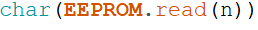
If you notice we are reading it in as a char. On line 22 we convert this char back to a string and append it to a string variable named string_Value with this command.

Notice how we use the String() to convert it. Also we use the += operator to append. It does the same as if you would use this code: string_Value=string_Value+ "some string". As I said in the title "Simple". Now you know the basics how to read your data out of memory.
Section Two: Connecting your IOT device to your WiFi network using the credentials stored in memory
Before you continue with this section first make sure you have entered your WiFi credentials in the ESP8266 huzzah breakout memory using the sketch in section 3 of Part 1 of this tutorial. We are building on top of that data.
Download sketch IOTdevice_read_Config_1_0.ino from this link. At first glance the sketch might look complicated, but that is only because we need to read information out of memory and then convert it to whatever format it needs to be in. If you look past the amount of code everything is straight forward
Near the top of the sketch (starting at line 24) we declare the following variables:
Notice that we declare 2 char arrays; ssid[30] and password[30]. This is needed because the code below (which is needed to connect to your WiFi router) needs this data type to work.

I'll explain this in more in detail in a bit. Next you see the integer ip_group. We use this variable to help parse the IP data out of memory. Each ip address is made up out of 4 groups of numbers, and we need a fifth one to store the last 3 digits of the gateway address. The last variable (string_IP) is used to temporarily store the ip info while we parse the data.
Reading Credentials out of Memory (ssid, Password)
Next we jump to the top of the setup() function. Lest look at the code starting at line 62;
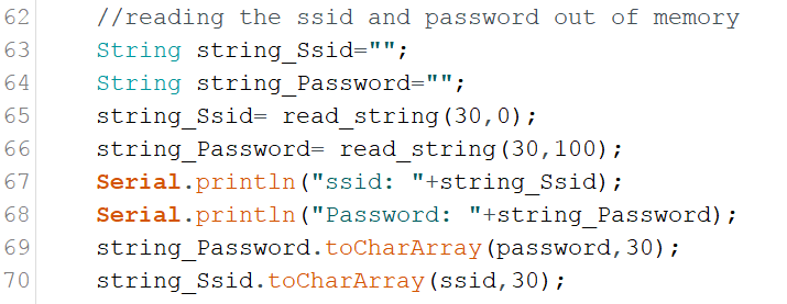
This block of code reads the WiFi routers ssid, and password out of memory. First two Strings() are declare to temporarily store the ssid, and password in. Then the function read_string(int Size,int Location) is called. You pass this function the location (in memory) of the data you want to read out of memory, and the size (in characters) of the data. It returns a String() containing the data you were looking for. Next the Strings gets converted into an Char Array. Remember that a Char Array variable had to use for the ssid and password, well here they are populate them with this command;

String.toCharArray(Char,Size) function converts a String into an Char Array. All you need is the String you want to convert, a Char Array and the size of Array. On line 69, and 70 we convert the temporary strings into the arrays that are going to be used to provide the SSID and Password credentials.
Next lets look at the read_string() function:
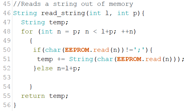
The read_string() function is strait forward. A for() loop that reads one character at a time out of memory. When it encounters the end of data string ';' character it exits the loop and returns the string as an result.
Configuring the IP information
The difficulty with configuring the IP information is that a string containing 4 groups of numbers needs to converted into 4 integers. Lets look at the code and see how it is done;
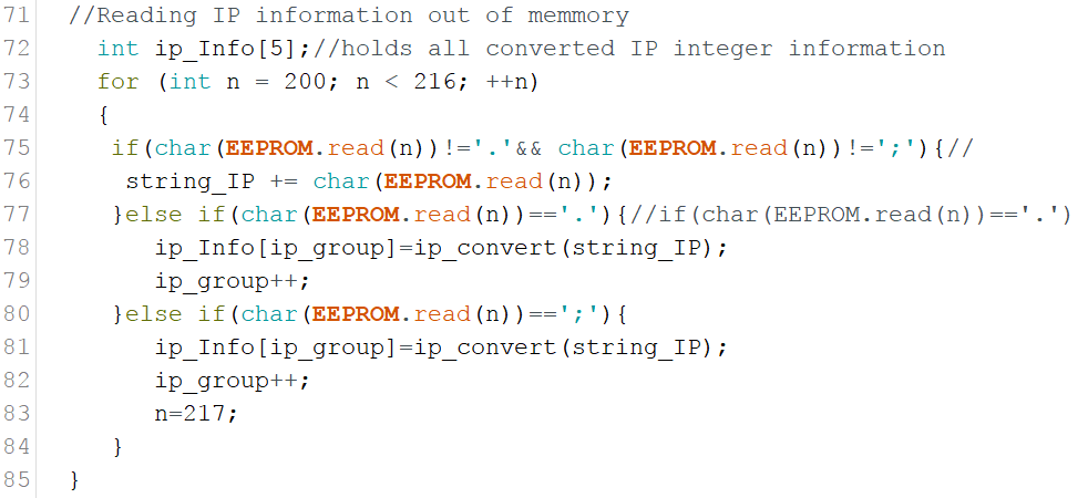
On line 73 a Array is declared of the integer type (ip_Info[5]. It can hold 5 groups of integers (The 4 from the IP, and one group for the gateway. Now remember when using Arrays, the first position always starts at 0. The ip_group variable is used to handle what IP group we are dealing with.
A simple for loop is used to read a string out of memory one character at a time. The if ()/else statement in the loop looks for the '.' and ';' characters (The '.' divides the 4 sets of IP numbers, and the';' is the end of string character) . When one of those characters is found it sends the string_IP string to the ip_convert(String) function. The ip_convert() function converts the string to an integer and returns it. The integer gets store in the ip_Info[] variable using the ip_group variable to determine what slot it gets stored in.
Lets explore the code for the ip_convert() function ;
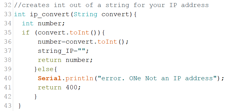
The ip_convert() function starts on line 34 of the sketch. It converts the string send to it to an integer. The syntax to convert a string into an integer is simple String.toInt(). We check if the string actually can be converted to an integer with the in statement on line 35. If it is possible to convert the string, the string_IP variable gets reset to empty and then returns the converted integer containing your IP information. If the string can't be converted to an integer it returns a value of 400 (You can use this for error checking, which I have not implemented).
Next the gateway information is read out of memory with the following code;

It uses the functions described above, saving me time and code size, and making things more streamlined :). Now it is time to put this all together and link the IP information (IP Stack) and credentials (ssid,password) to the ESP8266 and connecting it to your WiFi network. We do this with the following code;
click to enlarge
The IPAddress data type requires 4 integers divided by commas. The IP information stored in the ip_Info[] array gets use to populate the IP variables. Next we bind them to the development board using the WiFi.config() command, and it is time to connect to your WiFi router with the WiFi.begin() code.
The following code checks if the connection is working;
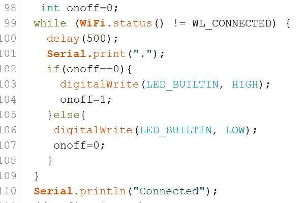
The While() loop uses the WiFi.status() function to check if it is connected. This does not check if the IP information is correct, it only checks that your credentials (ssid,password) are correct. The loop keeps cycling until it connects. I added the blinking onboard LED that blinks until connected.
Configuring the Web Server
I am not going to go deep into the webserver configuration as we have discussed it in detail in Part 1 of this tutorial. All I have done is created /on, and /off functions. The code for this can be found starting on line 113 of the sketch and the actual functions can be found starting on line 127 .
Compile this code and try to type http://insert your ip/on to turn the on board light on, and http://insert your ip/on to turn it off.
Section 3: Creating your user configurable IOT device
Download the completed sketch: complete_IOT_solution_1_0_2.ino here. I have also created a pdf with all functions in this sketch, their short descriptions and the line in the code where to find them. You can download it from here.
This is the final sketch of the tutorial. This sketch is basically WiFiAccessPoint_Write1_0.ino sketch(from Part 1), and the IOTdevice_read_Config_1_0.ino from the previous section mashed together to make one coherent sketch.
As a disclaimer I would like to say that this final sketch is not to be used without you doing thorough testing in a real world environment. I have done testing on it under controlled environment, but it has not had a monkey test done.
To make the two above mentioned sketches work I had to rework some of the variables used to deal with naming conflicts, but all the main functions and parts of the two parent sketches are there and intact.
To make the integration readable and understandable, I moved most of the code located in the setup() function of the parent sketches, and put them in their own functions (WAP(), and IOT()). I only left the shared items, like the setup of the webserver in the setup function.
The biggest change is really that I have altered the hardware configuration by adding a (spst) switch. This is basically a On and Off switch. The connection diagram can be found below. I have created the #define button_Pin 13 variable for the define the switch digital port.

I have set it up so that when the switch is in the On position you go into setup mode, and when it is Off to be in normal mode.
Another big change is part of the error checking. I have added some more comprehensive but still basic error checking with these functions:
- int ssid_error_Check(String content) on line 306
- int password_error_Check(String content) on line 321
- int ip_error_Check(String content) on line 344
- int gw_error_Check(String content) on line 382
These are very simple error check routines. They basically check if the string containing the data is the correct length, and if it contain characters that not allowed in the ssid, password, IP, and gateway. In the case of the IP I check for non alphanumeric characters with isAlpha(). This function returns a true when it contains non numeric characters. I do this with the following code:
It basically creates an error message that gets displayed in the input form if the IP address contains non Alphanumeric characters. A great place to see how to evaluate and analyse strings is this tutorial from the Arduino.cc people; link: https://www.arduino.cc/en/Tutorial/CharacterAnalysis.
The creation of the input web form also has seen some changes. I create a function called create_form(String ssidr,String passwordr,String ipr, String gwr) (on line 218). When you call it you pass it the ssid, password, ip, and the gw address. This is done in the error checking process. If one of the error checking function return a 1 (indicating an error) the input form is returned to the web browser with previously entered values and the appropriate error message. We use the following global error messages variables (declared on line 38).
String ssid_Arg;// Error message for ssid input
String password_Arg;// Error message for password input
String ip_Arg;// Error message for ip input
String gw_Arg;// Error message for gateway input
Compile and upload the sketch and take it for a run. First set the switch into the setup configuration and type in your WiFi credentials. See how the error checking works (remember it is really basic, you might want to add some more checks to it). Then throw the switch into normal operation mode and see how it connects to your WiFi router. Go to the root / of your device with your web browser and how to turn the onboard led on and off.
This completes this tutorial. If you have further questions leave them in the comment section below and I'll try to answer them as quick as possible. I hope you enjoyed this tutorial and it increased your knowledge base so you can become a more accomplished maker.
If you like this tutorial and want to see more of this please subscribe to my periodical Newsletter by filling out the form below, or follow me on Facebook by clicking on this link, and click the Like button on my Facebook page.