

Project: Creating A NodeMCU Data-Logger Using The Cloud
In this sample project we are going to build a NodeMCU data logger that uses the Adafruit cloud to store the temperature and humidity data. To make it even more exciting we are putting the NodeMCU to sleep in the periods that we are not transmitting the data to the cloud.
| Please put some money in the tip jar by clicking on the donate button to support me so I can continue creating contend like this. P.S. please donate more than $1 as PayPal takes minimum $0.30 per transaction |
In this project we are going to build a NodeMCU data logger that uses the Adafruit cloud to store the temperature and humidity data. To make it even more exciting we are putting the NodeMCU to sleep in the periods that we are not transmitting the data to the cloud.
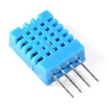
The basics of this project are as follows. First we are going to connect a Temperature Humidity sensor (The DHT11 or DHT22) to the NodeMCU. After getting that to work we are going to setup a feed on the Adafruit IO cloud. Then we will write the code to send the temperature data to the cloud using the MQTT protocol. Finally we add the sleep function of the ESP8266 to the mix.
This sounds like a lot, but you will actually see it is a very simple and straightforward process. If you look back a couple of weeks I build the same datalogger only using the Arduino Pro Mini, a RTC, and an SD card writer/reader breakout board. For this project we will only require A NodeMCU, a DHT11/22 sensor, and a connection to the interweb.
Index
List Of Materials Needed For This Project


Connecting the DHT11/22 Sensor
To connect the DHT11/22 family of sensors we are going to use a library specifically designed for the ESP8266 micro controller or compatibles. The library is called DHTesp.h and needs to be installed using the Arduino IDE Library manager.
You can find the Library Manager under the Sketch menu and selecting the Include Libraries, and then the Manage Libraries option. In the search bar type dht to only show the libraries related to the DHT11/22 sensor. Click the more info link on the DHT library for the ESPx. A dropdown will appear where you select the latest version of the driver, then click the install button.
Click To Enlarge
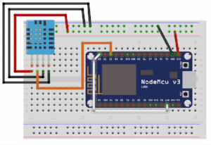
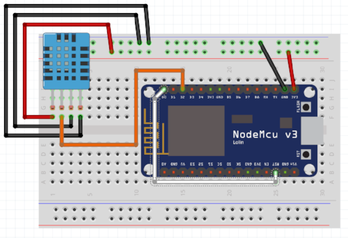
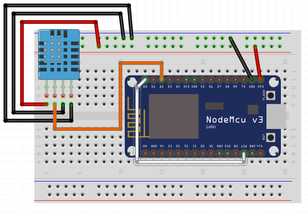
I selected this library as it takes in consideration the slow communication speed of the DHT11/22 when running on 3.3v. Next we connect the sensor as follows (with the grid facing you)
| DHT 11/22 | NodeMCU | Arduino equivalant |
| Pin 1 VCC In | 3.3V | 3.3V |
| Data Out | Pin D2 | Digital Pin 4 |
| GND | GND | GND |
| GND | GND | GND |
| Please put some money in the tip jar by clicking on the donate button to support me so I can continue creating contend like this. P.S. please donate more than $1 as PayPal takes minimum $0.30 per transaction |
If you like this sample project and want to see more of this type of content, consider putting some money in the tip jar by clicking the Donate button. If you want to see more of this content subscribe to my newsletter with the form below or follow me on Facebook. This link will take you to my Facebook page. Hope to see you soon, have a great day and bye for now

Tutorial: Intro to the NodeMCU
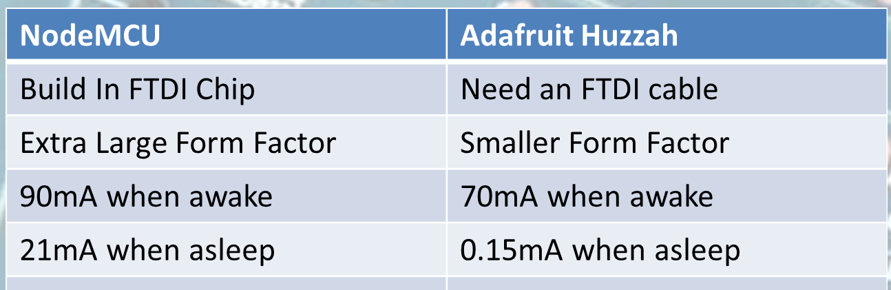
This tutorial is a simple guide to get started with the NodeMCU one of the most popular forms of the ESP8266 on the market right now. The NodeMCU is a powerful board that is good on the pocket book, but has its drawbacks. We are going to explore how to set this board up with the Arduino IDE, and some other simple tips and trick to get you started.
| Please put some money in the tip jar by clicking on the donate button to support me so I can continue creating contend like this. P.S. please donate more than $1 as PayPal takes minimum $0.30 per transaction |
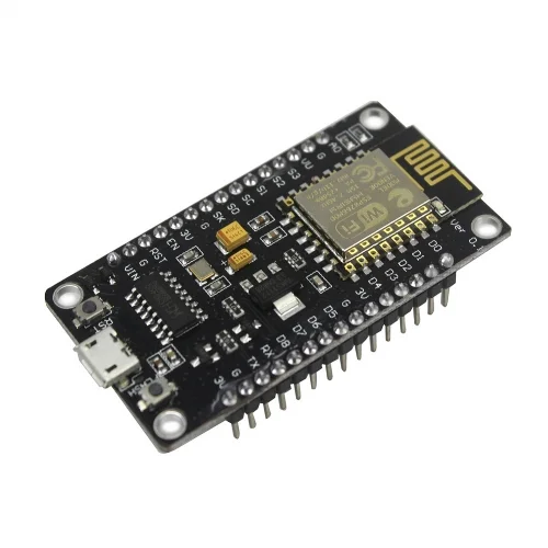
This tutorial is a simple guide to get started with the NodeMCU one of the most popular forms of the ESP8266 on the market right now. The NodeMCU is a powerful board that is good on the pocket book, but has its drawbacks. We are going to explore how to set this board up with the Arduino IDE, and some other simple tips and trick to get you started.
Material Needed For This Tutorial


Driver Installation
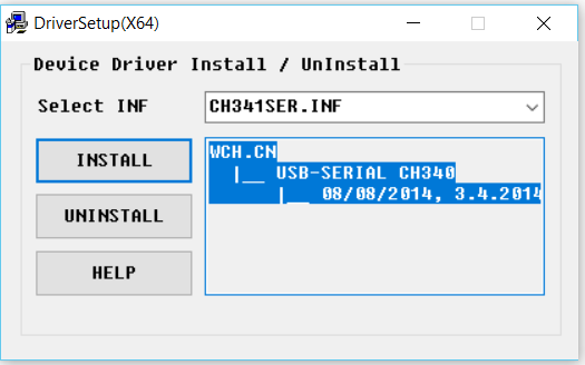
One of the drawbacks of this board is that you have to install a usb drivers to communicate with this board. You can download the driver from here. Before you try to install the driver be sure you have Administrator privileges on your computer.
After you have downloaded the driver installation package, and you have Administrator privileges you can start the installation. Use a Micro USB Type-B cable that is rated for data transfer. Follow these steps to install your Driver
- Download Driver
- Connect your NodeMCU to your computer using the USB cable.
- Run the driver installation package you downloaded as Administrator
- Click the install button
The driver should install without any problems. The main issue that people have is either not connecting the NodeMCU to the computer before starting the install, or not having the right cable, or not having the correct privileges on your computer. If your driver install fails first make sure all the above mentioned requirements have been met. If it still doesn’t work you have entered the realm of unsupported freeware, and sadly are on a journey of exploration that can be painful. I have not seen it fail when all the requirements have been met.
Preparing the Arduino IDE
If you have never worked with an ESP8266 type of board you need to install the drivers and libraries for this in your Arduino IDE. . The people at Sparkfun have a nice tutorial for this. You go there by clicking on this link: https://learn.sparkfun.com/tutorials/esp8266-thing-hookup-guide/installing-the-esp8266-arduino-addon
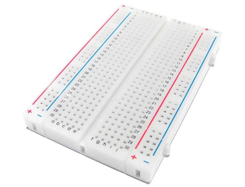
The NodeMCU form factor
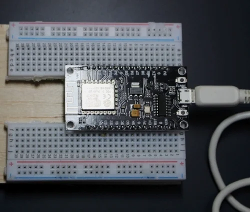
You might have noticed by now that the NodeMCU is a bit large. It won’t fit on a regular size breadboard (well it does but you have no room to connect anything to it). What I have done to make it fit is use a dremel tool and cut a normal breadboard in two along the spine (See picture) Now it will fit perfectly.
Pinouts
This is one of the greatest drawbacks of the NodeMCU for beginner users. The labels on the NodeMCU don’t correspond to the digital pins (GPIO pins) we know and love when working with Arduino compatibles. You need image ? to make sense of it.
For example pin D1 on the board corresponds with GPIO 5 (Digital pin 5 on your Arduino). The best thing to do is keep that image handy as a guide to find out what pin does what, and how they correspond to the Arduino world.
Specs
The board runs at 3.3v, and all pins can have a max load of 12mA and a 3.3v logic. When buying breakout boards or other components make sure they run on those specs. It also means you have to be careful when using the pins from the NodeMCU to power components. 12mA is not a lot and this makes it easy for you to overload a pin and fry your board. The board also has only one analog port A0, and it is for input only (like all other ESP8266).
You can power the board with an external power supply no greater than 12V. The documentation is spars, but what I have found is that it can handle 20V but the volt regulator will get dangerously hot. This is why I recommend having a power supply that supplies no more than 12V.
Onboard LED
Often we use an onboard LED in the development phase to error check. This board does not have the LED connected to pin/gpio13, instead it has it connected on pin/gpio 2.
Uploading a Sketch
Next we are going to upload the blink sketch to the NodeMCU. If you have followed the above steps you should have installed the hardware driver (driver name) and the Arduino IDE drivers and libraries we are ready to upload a blink sketch.
Configuration for the NodeMCU
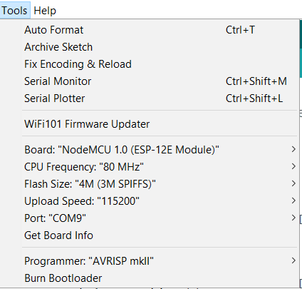
We start by selecting the NodeMCU 1.0 (ESP-12 Module) under the board options in the Tools menu (See Image for the complete configuration). See Image ? . The only thing that could be different on your computer is the COM port. You just need to select the COM port available to you under the Tools menu Port option.
Below you find the sample sketch to make the onboard LED flash on the NodeMCU
int LED_PIN= 2;

void setup() {
  // initialize digital pin LED_BUILTIN as an output.
  pinMode(LED_PIN, OUTPUT);
}

// the loop function runs over and over again forever
void loop() {
  digitalWrite(LED_PIN, HIGH);   // turn the LED on (HIGH is the voltage level)
  delay(1000);                       // wait for a second
  digitalWrite(LED_PIN, LOW);    // turn the LED off by making the voltage LOW
  delay(1000);                       // wait for a second
}
In Closing
Check back in about 14 days when I build a more elaborate project with the NodeMCU to see what you can do with this board. But for now if you enjoyed this tutorial please subscribe to my newsletter by filling out the form below, or go to my Facebook page by clicking on the link and follow and like the page. By doing his you will get an alert every time I post a new article. If you have questions or suggestions please email at akurk@thearduinomakerman.info me or leave it in the comments below. Have a great day and see you next time.