Project, Tutorial, NodeMCU Ab Kurk Project, Tutorial, NodeMCU Ab Kurk

Project: Creating A NodeMCU Data-Logger Using The Cloud

In this sample project we are going to build a NodeMCU data logger that uses the Adafruit cloud to store the temperature and humidity data. To make it even more exciting we are putting the NodeMCU to sleep in the periods that we are not transmitting the data to the cloud.

Please put some money in the tip jar by clicking on the donate button to support me so I can continue creating contend like this. P.S. please donate more than $1 as PayPal takes minimum $0.30 per transaction
NodeMCU_DHT11.22.sleep-configPNG.PNG

In this project we are going to build a NodeMCU data logger that uses the Adafruit cloud to store the temperature and humidity data. To make it even more exciting we are putting the NodeMCU to sleep in the periods that we are not transmitting the data to the cloud.

The basics of this project are as follows. First we are going to connect a Temperature Humidity sensor (The DHT11 or DHT22) to the NodeMCU. After getting that to work we are going to setup a feed on the Adafruit IO cloud. Then we will write the code to send the temperature data to the cloud using the MQTT protocol. Finally we add the sleep function of the ESP8266 to the mix.

This sounds like a lot, but you will actually see it is a very simple and straightforward process. If you look back a couple of weeks I build the same datalogger only using the Arduino Pro Mini, a RTC, and an SD card writer/reader breakout board. For this project we will only require A NodeMCU, a DHT11/22 sensor, and a connection to the interweb.  

Index

List Of Materials Needed For This Project

Connecting the DHT11/22 Sensor

To connect the DHT11/22 family of sensors we are going to use a library specifically designed for the ESP8266 micro controller or compatibles. The library is called DHTesp.h and needs to be installed using the Arduino IDE Library manager.

You can find the Library Manager under the Sketch menu and selecting the Include Libraries, and then the Manage Libraries option. In the search bar type dht to only show the libraries related to the DHT11/22 sensor. Click the more info link on the DHT library for the ESPx. A dropdown will appear where you select the latest version of the driver, then click the install button.

Click To Enlarge

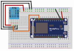
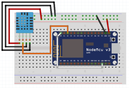
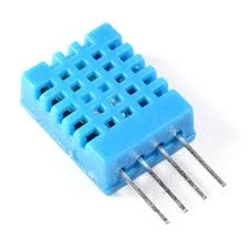
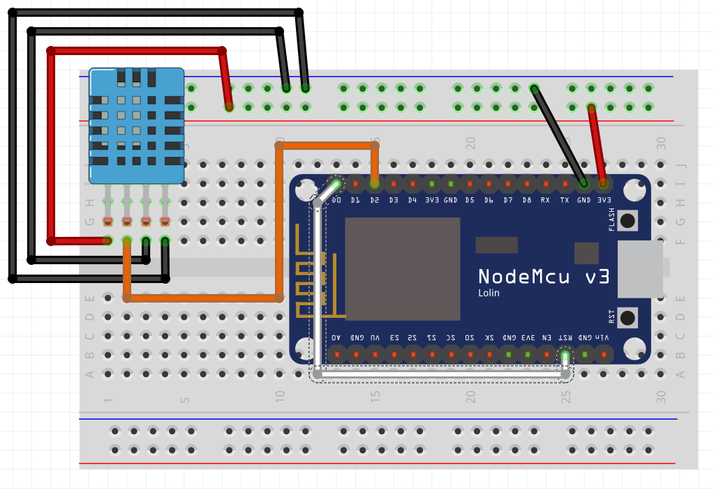
I selected this library as it takes in consideration the slow communication speed of the DHT11/22 when running on 3.3v. Next we connect the sensor as follows (with the grid facing you)

Click Image to enlarge

Lets look at the code to make the DHT11/22 work. This is the Sample sketch is based on the sketch that comes with the Library called. You can download it from here. First lets look at the library and object deceleration.

#include "DHTesp.h"
DHTesp dht;

This is straight forward; we include the library and declare the dht object that allows us to communicate with the internal code of the library and thus communicate with the DHT hardware. Next we will look at the setup() function 

void setup()
{
  Serial.begin(115200);
  Serial.println();
  Serial.println("Status\tHumidity (%)\tTemperature (C)\t(F)\tHeatIndex (C)\t(F)");
  dht.setup(4); // data pin 4
}

Again straight forward stuff. We begin serial communication with the NodeMCU, then we print some stuff to the Serial monitor. The only thing of consequence is the dht.setup(4). This is where you tell the software what hardware pin we use. The original sketch uses Arduino digital pin 2, but because we are going to use that one later on in this project we use digital pin 4 (NodeMCU D2). Next we move to the main loop() function.

void loop()
{
  delay(dht.getMinimumSamplingPeriod());

  float humidity = dht.getHumidity();
  float temperature = dht.getTemperature();

The delay(dht.getMinimumSamplingPeriod()); is really what makes this library special. The DHT11/22 is a very slow communicator, using it on 3.3V makes it even slower. This line allows the software to communicate with the hardware by creating a moment where the software stops until the hardware is ready to communicate. The next two lines get the humidity and the temperature readings (in Celsius ) from the sensor. 

  Serial.print(dht.getStatusString());
  Serial.print("\t");
  Serial.print(humidity, 1);
  Serial.print("\t\t");
  Serial.print(temperature, 1);
  Serial.print("\t\t");
  Serial.print(dht.toFahrenheit(temperature), 1);
  Serial.print("\t\t");
  Serial.print(dht.computeHeatIndex(temperature, humidity, false), 1);
  Serial.print("\t\t");
  Serial.println(dht.computeHeatIndex(dht.toFahrenheit(temperature), humidity, true), 1);
}

In this block of code we print the temperature and humidity in different formats to the serial monitor. This code is so easy that I don't really need to say a lot about it. Upload this to your NodeMCU and see the result

The Cloud

The Cloud is just a fancy way of saying internet storage. We are going to use the Adafruit IO cloud. The Adafruit IO cloud allows you to store data for up to a month and visualize it in different ways. To get started go to this link: https://io.adafruit.com/ and create a free account.

For out project we are going to create 2 feeds. A feed is what your sketch is going to communicate with, and store your data. 

Creating a feed

To create a feed click this link: https://learn.adafruit.com/adafruit-io-basics-feeds/overview which takes you to the Adafruit tutorial how to create a feed. They did an amazing job, so why should I duplicate it. You need to create 2 feeds, one named temp (going to store the temperature) and one called humidity (to store the humidity data in). It is important that you call them exactly the same, and they are case sensitive. 

The Libraries

There are two ways of getting the libraries needed. The first one is by downloading them from github by clicking on this link: https://github.com/adafruit/Adafruit_MQTT_Library. The second one is using the Arduino IDE library manager the same way as you installed the library for the DHT 11/22 sensor. The only difference is that you type in "adafruit mqtt" in the search bar. I installed version 0.20.1 of this library.

Click TO Enlarge

The code

Before we continue I recommend you download the sketch by clicking on this link. It is always a good idea to have the code to follow along with the explanation. As usual we start with the deceleration and loading of libraries and global variables. The library section is an easy one.

#include <ESP8266WiFi.h>
#include "Adafruit_MQTT.h"
#include "Adafruit_MQTT_Client.h"
#include "DHTesp.h"

DHTesp dht;

The ESP8266WiFi.h library is used to create a connection to your WiFi router. The Adafruit_MQTT.h, and the Adafruit_MQTT_Client.h are used to communicate with their cloud service. And the rest of this code is already explained as it is used for the DHT type sensor. 

Next we will setup the configuration needed to connect to your WiFi router.

#define R_SSID       "...your SSID..."
#define PASS       "...your password..."

The R_SSID is the name of your router, replace the text between the "" with the name of your WiFi router, the PASS is your routers password. Replace the text between the "" with your routers password. The next section we are setting up the Adafruit IO cloud variables.

#define AIO_SERVER      "io.adafruit.com"
#define AIO_SERVERPORT  1883                   // use 8883 for SSL
#define AIO_USERNAME    "...your AIO username (see https://accounts.adafruit.com)..."
#define AIO_KEY         "...your AIO key..."

The naming of the variables are self explanatory. The only thing you have to supply is your username. Type it between the quotation marks behind the AIO_USERNAME  You created this when you created the 2 feeds earlier on, and the AIO_KEY, which you can generate or copy by clicking on this link: https://io.adafruit.com/  logging in to your account and clicking on the View AIO Key link. Here you can either copy the key, or if you have not done so generate a key. Place the key between the quotation marks .

Next we are going to look at the code to create the feed objects. As explained in the Adafruit tutorial, the feeds is where you publish your data to. The code for the feed objects looks like this

Adafruit_MQTT_Publish Temperature = Adafruit_MQTT_Publish(&mqtt, AIO_USERNAME "/feeds/temp");
Adafruit_MQTT_Publish Humidity = Adafruit_MQTT_Publish(&mqtt, AIO_USERNAME "/feeds/humidity");

The names we use to communicate with the objects are "Temperature" to communicate with the temp feed, and the "Humidity" object to communicate with the humidity feed. The function used works like this;

Adafruit_MQTT_Publish(mqtt object, AIO_USERNAME "/feeds/name of the feed") . If you have named your feeds different or want to name them different this is the part of the code you alter to make that happen, but be aware that the name of the feed needs to be the same as the name you used in the cloud.

Next we create the WiFi client object we are going to use to connect to the Adafruit MQTT server  with this line of code:

WiFiClient client;

Now we are going to create the MQTT object used to connect and communicate  with the Adafruit MQTT server. We do this with this line of code:

Adafruit_MQTT_Client mqtt(&client, AIO_SERVER, AIO_SERVERPORT, AIO_USERNAME, AIO_KEY);

If you noticed all previously created variables are used in this line. the mqtt object created is used to further communicate to the MQTT server and feeds throughout the sketch. 

Next we are looking at the setup() function. Here we are going to connect to your WiFi router.

  WiFi.begin(R_SSID, PASS);
  int counter=10;
  while (WiFi.status() != WL_CONNECTED) {
    delay(500);
    Serial.print(".");
    counter--;
    if(counter==0){
      // reset me
        ESP.reset();
    }
  }

The Wifi.begin() starts the connection to your WiFi router. It uses the R_SSID and PASS variables to connect to your WiFi router. This can take a bit of time, this is why we have a while() loop that checks the status of the WiFi connection with the WiFi.status() function. This function can have these states:

  •     WL_IDLE_STATUS      
  •     WL_NO_SSID_AVAIL   
  •     WL_SCAN_COMPLETED  
  •     WL_CONNECTED        
  •     WL_CONNECT_FAILED   
  •     WL_CONNECTION_LOST  
  •     WL_DISCONNECTED    

I am not sure if this is an all inclusive list, but these are the most common ones. The loop will run as long as the WiFi.status() function doesn't returns  the value  WL_CONNECTED. Now sometimes this can be forever even when your WiFi SSID and password are correct.

To prevent this from happening I have put in the int counter=10; variable. With the counter--; we subtract 1 of the value of this variable. Next we have the if(counter==0) statement that lets the loop run for about 10 cycles. When the counter variable has a value of 0 the if() statement is true and the ESP.reset() will reset  your NodeMCU and restart the connection process. This basically prevents you from entering the loop of no return.

When the connection to the WiFi router is successful we are passed on to the main loop() of the sketch. The first line of consequence is the MQTT_connect(); . This send us to the function that will connect us to the MQTT server.

  if (mqtt.connected()) {
    return;
  }

The first thing we do is to see if we are still connected from a previous loop with the if() statement. If mqtt.connected() is true the return; command will exit us from the function back to the main loop preventing us from unnecessarily taxing the MQTT server.

If we are not connected we end up here;

  uint8_t retries = 5;
  while ((ret = mqtt.connect()) != 0) { // connect will return 0 for connected
       Serial.println(mqtt.connectErrorString(ret));
       Serial.println("Retrying MQTT connection in 5 seconds...");
       mqtt.disconnect();
       delay(5000);  // wait 5 seconds
       retries--;
       if (retries == 0) {
         // reset me
        ESP.reset();
       }
  }

Here we end up in another loop to facilitate the connection to the MQTT server. The while() loop will continue until mqtt.connect() returns a value of 0. In the loop the mqtt.disconnect(); resets the connection to the MQTT server to prevent it from being in a weird state. We wait 5 seconds to give everything a rest period with delay(5000);. The retries counter value is reduced by 1. As with the connection to the WiFi router this could become an endless loop. So by the time we have gone through this process 5 times and we are still not connected the  ESP.reset() will reset the NodeMCU and we start the whole process again.

After we are successful connecting to the MQTT we are send back to the main loop and we are ready to finally upload some data to that cloud.

  delay(dht.getMinimumSamplingPeriod());//waits for the DHT sensor to respond

  float humidity = dht.getHumidity();  //Gets the humidity from the sensor
  float temperature = dht.getTemperature();//gets the temperature in celsius from the sensor

First we get the temperature and humidity data with the above code. We explained the function of this already. Now we have the data we can send it to the cloud.

  if (! Temperature.publish(temperature)) { 
    Serial.println(F("Temperature Failed"));
  } else {
    Serial.println("Temperature: "+String(temperature)+"C");
  }
  if (! Humidity.publish(humidity)) {
    Serial.println(F("Humidity Failed"));
  } else {
    Serial.println("Humidity: "+String(humidity)+"%");
  }

The actual important parts of this code are Temperature.publish(temperature) and Temperature.publish(humidity) statements. If you notice we use the feed object we created in the declaration section of the code and use the .publish() to send it so the cloud. The if() statement is only there to do error checking.  The .publish() returns a value of 0 when it is successful, if not we just write a error statement to the serial monitor. The final line in the main loop() is a delay(30000); which makes the sketch wait 30 seconds before continueing for another go. 

Sleep Mode

Sometimes the logging projects get put in an area where no power outlets are available. If you are running the project on a battery pack you need to put your NodeMCU to sleep when not in use. If you look back a couple of weeks back you see that I created a data logger very similar to this project only we used an Arduino Pro mini. It is a lot harder to wake up an Arduino Pro Mini.

To wake up the NodeMCU only one jumper wire is required, after that no additional hardware is required. All we do is run a jumper wire from pin D0 to the RST pin

NodeMCU_DHT11.22.sleep-configPNG.PNG

You can download the sketch mqtt_NodeMCU_sleep_v1_0b.ino from here. The only difference to the code is that we alter the delay(30000); in the main loop to delay(1000); and add this line just below it; ESP.deepSleep(30e6);

The ESP.deepSleep(microseconds) function puts the NodeMCU into a deep sleep for the time you entered between the brackets in microseconds. We want to put the NodeMCU to sleep for 30 seconds, that is 30000000 microseconds or a 30 with 6 zeros or 30e6.

The process is simple the ESP.deepSleep() function switches off all functions of the NodeMCU except for its internal clock. You basically set an alarm, and when the time is up it pulls the D0 pin low and doing this also pulling pin RST low. This will reset the NodeMCU and the process will start over as if you just plugged in the power to the controller. 

In Closing

I wanted to quickly compare the NodeMCU with the Adafruit Huzzah. If you are going to connect your project to a power supply the NodeMCU is a good solution as you don't have to buy special cables, you could even power it with a USB charger/cable.

If you are going to connect your project to a battery pack the Adafruit Huzzah is your board. While in sleep mode the NodeMCU uses almost 21mA more then the Adafruit Huzzah. Check out the diagram below for the info

Compare.PNG


This is the end of this project. I will go deeper into the sleep modes available for the NodeMCU on a later date. This is a sample project so the code can certainly be refind with better error checking. Also the DHT11 can sometimes give false readings when used in this way. Putting a for() loop where you read the data out of the sensor a couple of times before you use it can make it more accurate. 

DHT 11/22 NodeMCU Arduino equivalant
Pin 1 VCC In 3.3V 3.3V
Data Out Pin D2 Digital Pin 4
GND GND GND
GND GND GND
Please put some money in the tip jar by clicking on the donate button to support me so I can continue creating contend like this. P.S. please donate more than $1 as PayPal takes minimum $0.30 per transaction

If you like this sample project and want to see more of this type of content, consider putting some money in the tip jar by clicking the Donate button. If you want to see more of this content subscribe to my newsletter with the form below or follow me on Facebook. This link will take you to my Facebook page. Hope to see you soon, have a great day and bye for now

Subscribe to our mailing list

* indicates required
Email Format
Read More
Project, Huzzah ESP8266 Ab Kurk Project, Huzzah ESP8266 Ab Kurk

Project: IOT Christmas Lights Display

A couple of year’s back I bought one of the Neopixel light strings from Adafruit. I think it was 200 leds. I used them one season and put them away. This Christmas I decided to make an IOT Christmas light display out of it just above our horizontal blinds.

To do this I used the code explained in  the Tutorial:Storing WiFi Configuration On Your ESP8266 Using The EEPROM Library Made Simple Part 1 and Tutorial part 2. I also used code from the Adafruit Neopixel example code and integrated it with my base code to create an IOT device from the tutorial.

Please put some money in the tip jar by clicking on the donate button to support me so I can continue creating contend like this. P.S. please donate more than $1 as PayPal takes minimum $0.30 per transaction

A couple of year’s back I bought one of the Neopixel light strings from Adafruit. I think it was 200 leds. I used them one season and put them away. This Christmas I decided to make an IOT Christmas light display out it. 

To do this I used the code explained in  the Tutorial:Storing WiFi Configuration On Your ESP8266 Using The EEPROM Library Made Simple Part 1 and Tutorial part 2 as my base code. I also used code from the Adafruit Neopixel example code and integrated it with my base code. The complete IOT Christmas Light Display code can be downloaded from this link. 

I won’t explain the base code again as I have a great tutorial that already does this. I will just explain the steps I took adding the Neopixel code and how to control them

I split this project into the steps I tackled to integrate the  Neopickel code into the IOT code. You can download the complete sketch here.

INDEX

Here is a list of the hardware I chose to use:

  • Huzzah ESP8266 Breakout
  • 8-channel Bi-directional Logic Level Converter - TXB0108 from Adafruit
  • On/Off toggle switch
  • 10K Resistor
  • 5V FTDI cable
  • WS2812 Addressable Light String (200 LED)
  • 5V  2A power supply (depending on how many lights the Amperage will vary ) 


Step 1 Create the colourset() function

This function sets the light string colour. I started with copying this code from the Adafruit example sketch. For an explanation of this code go to the Adafruit tutorial that explains it in detail. But here are the highlights.

When calling the colourset() function you pass it the RGB value of the colour you want the led’s to turn. In the for() loop you see the NUMPIXELS variable. It has been set on line 61 and contains the number of LED’s your lightstring contains.

void colourset(int r,int g,int b){
  for(int i=0;i<NUMPIXELS;i++){
      // pixels.Color takes RGB values, from 0,0,0 up to 255,255,255
          pixels.setPixelColor(i, pixels.Color(r,g,b)); // sets the colour
          pixels.show(); // This sends the updated pixel color to the hardware.
          colour=0;
       }
}

Step 2 calling the colourset() function

This is done in a Switch()/case statement on line 217 in the loop() function. It uses a int variable colour (yes this is the correct spelling in Canada) that gets set through a web form. If you look at option 4 in the case statement you see a bunch of code. This code randomly changes the colours of the string creating a rainbow affect.

  switch(colour){
    case 0:
    
    break;
    case 1:
    colourset(255,0,0);//Red
    break;
    case 2:
    colourset(0,255,0);//Green
    break;
    case 3:
    colourset(244,229,66);//yellow
    break;
    case 4:
     uint16_t i, j;
      breakon=0;
      Serial.println("rainbow");
      for(j=0; j<256*5; j++) { // 5 cycles of all colors on wheel
        for(i=0; i< pixels.numPixels(); i++) {
          pixels.setPixelColor(i, Wheel(((i * 256 / pixels.numPixels()) + j) & 255));
          server.handleClient();
          if(breakon==1){
            Serial.println("breakon");
            Serial.println("Colour: "+ String(colour));
            breakon=0;
            j=256*5+1;
            i=pixels.numPixels()+1;
            
          }
        }
        server.handleClient();
        if(breakon==1){
            Serial.println("breakon");
            Serial.println("Colour: "+ String(colour));
            breakon=0;
            j=256*5+1;
            i=pixels.numPixels()+1;
            
          }
        pixels.show();
        delay(50);
      }
      //colour=0;
    
    break;
    case 5:
    colourset(32,58,229);//blue
    break;
    case 6:
    colourset(204,11,229);//purple
    break;
    case 7:
    colourset(r_Arg,g_Arg,b_Arg);
    break;
    case 8:
    colourset(0,0,0);//off
    break;
  }
}


For a better understanding of this rainbow code, look in the Adafruit tutorial for the Neopixels. I modified the code a bit. The reason for this is that it uses 2 nested for() loops that make it hard to communicate with the microcontroller. If you remember that the web server uses this function server.handleClient() to read request from the server.

As long as your sketch is in a for() loop the request won’t be honored. This is why I created a variable called breakon. If it has a value of 1 the if() statements I have added to the code will terminate the for() loops and will allow the microcontroller to fulfill  the web requests. The value of the breakon variable gets set to 1  in the handleroot() function on line 309 when a server request is made. It gets set back to 0 in the switch()/case statement in the loop() function

Screenshot_20171213-124148.jpg

Step 3 Creating the web input screen

The web input screen html code is setup in function colour_form() starting on line 371 . It contains several forms nested in a table structure. It is a normal form that when you press the button makes a request to the root of your server and sending a hidden field with an integer that corresponds with the colour you want to set.

<input type=\"hidden\" name=\"colour\" value=\"1\">"

The value of this hidden field gets used to set the colour variable.

        colour=server.arg("colour").toInt(); 

The colour variable then gets used to operate the Switch()/case statement in the loop() function.

Step 4 The handleroot() function

In this function we use the server.Arg(“colour”) value to set the colour variable. It also sets the breakon variable to 1 so we can exit out of the for() loops in the rainbow mode.  You can find the code on line 319

      }else if (server.hasArg("colour")){
        Serial.println("Colour is set to: "+server.arg("colour"));
        colour=server.arg("colour").toInt(); 
        breakon=1;
      }

It also reads the RGB value from the web form option to create your own colour. The code can be found on line 311

      if(server.hasArg("RED") && server.hasArg("GREEN")&& server.hasArg("BLUE")){
         Serial.println("RGB");
        colour=server.arg("ssid").toInt();
        r_Arg=server.arg("RED").toInt();
        g_Arg=server.arg("GREEN").toInt();
        b_Arg=server.arg("BLUE").toInt();
       breakon=1;
      
      }else if (server.hasArg("colour")){

Step 5 make sure that the libraries are installed

The final steps are to make sure you copy the #include <Adafruit_NeoPixel.h> library and the appropriate variables needed to run this library

  •  #define PIN            12// sets the digital pin to send the data to
  •   #define NUMPIXELS      200 //number of led’s on your light strings
  • Adafruit_NeoPixel pixels = Adafruit_NeoPixel(NUMPIXELS, PIN, NEO_GRB + NEO_KHZ800); //sets up the light string

Step 6 The hardware setup

Click To Enlarge


Setup switch

It’s explained in the IOT tutorials. We have connected it to Digital pin 13.

LED Light string

The LED light string  is addressable, using the WS2812 LED. It uses a 5v logic and the ESP8266 uses 3.3v logic. This is why we used the  Adafruit TXB0108 logic level. I used this one because it is easy to use, and I had one laying around. But what the logic level does is convert the 3.3v logic info send from the Huzzah and converts it to 5v so the LED string can operate. We use digital pin 12 on the Huzzah for this. Look at the schematic above how it has been connected.

Another thing to think about is an appropriate power supply. Each of those led’s can draw up to 55mA. All the details about this can be found in the Adafruit tutorial. 


If you have any questions leave them in the comments and I get back to you as soon as possible. If you like this project and would like to see more of it you can subscribe to my news letter using the form below.

Subscribe to our mailing list

* indicates required
Email Format
Read More