


Tutorial:Storing WiFi Configuration On Your ESP8266 Using The EEPROM Library Made Simple Part 2
This is Part 2 of a 2 part tutorial that will simplify the way you can store your WiFi configuration on an ESP8266 using the EEPROM library. With this knowledge you can then build Internet Of Things (IOT) projects that can be configured by web form. This will enable to change passwords or IP configuration when needed without having to recompile your sketch.
In part 2 you will learn howto read information "your stored in memory in part one" out of memory. How to use it to configure your IOT device to connect to your WiFi network, and make it user configurable by combining Part 1 and 2 in one sketch
| Please put some money in the tip jar by clicking on the donate button to support me so I can continue creating contend like this. P.S. please donate more than $1 as PayPal takes minimum $0.30 per transaction |
This is Part 2 of a tutorial Storing WiFi Configuration On Your ESP8266 Using The EEPROM Library Made Simple. If you have not read Part 1 I would recommend you do. Here is the link to Part 1. In this tutorial (Part 1/Part 2) I explain how to build a user configurable Internet Of Things devide
In Part 2 we are going to look at how to read the data we stored in Part 1 from memory. We are going to use this to configure your IOT device and connect to your local WiFi network. The end result of this tutorial will be an IOT device that will turn the on board LED on and off through a web browser, and enable you to alter your WiFi configuration through a web form all in one device.
This Tutorial will have three sections. In Section One: Read data out of memory using the EEPROM Library; you will see how to read data out of memory using the EEPROM library. In Section Two: Connecting your IOT device to your WiFi network using the credentials stored in memory; you will learn how to connect your IOT device with the data stored in memory to your local WIFI network, and be able to connect to it with a web browser. In Section 3: Creating your user configurable IOT device ; you will see how to combine what you have learned in Part 1 and Part 2 of this tutorial to create a final project with a WiFi Access Point to configure your WiFi credentials, and an Internet Of Things device that allows you to turn the on-board LED on and off using a web browser
MATERIALS NEEDED IN THIS TUTORIAL
- Adafruit Huzzah Breakout
- 5v FTDI cable
- bread board
- On/OFF switch ( SPST Toggle Switch)
- Some jumper wires
- 10K ohm resistor
Sample Sketches
Section One: Read data out of memory using the EEPROM Library
Download the eeprom_read_1_0.ino sketch from this link. This sketch is going to read the SSID out of memory that you wrote to the ESP8266 in the last example (WifiAccessPoint_Write_1_0.ino) in Part 1 of this tutorial. If you recall that our SSID was stored in memory location 0, and had a max length of 30 characters. We used the ';' character as the end of string character.
Looking at the sketch we see that only one part has changed in this sketch compared to the writing sketch in Part 1. Instead of writing we are reading from memory. On line 21 in the if statement we are reading data with this command:
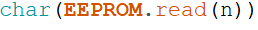
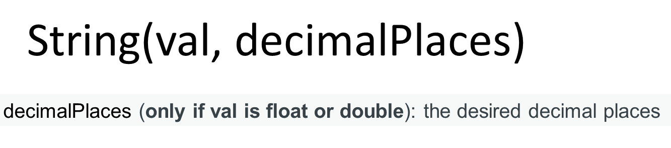
If you notice we are reading it in as a char. On line 22 we convert this char back to a string and append it to a string variable named string_Value with this command.

Notice how we use the String() to convert it. Also we use the += operator to append. It does the same as if you would use this code: string_Value=string_Value+ "some string". As I said in the title "Simple". Now you know the basics how to read your data out of memory.
Section Two: Connecting your IOT device to your WiFi network using the credentials stored in memory
Before you continue with this section first make sure you have entered your WiFi credentials in the ESP8266 huzzah breakout memory using the sketch in section 3 of Part 1 of this tutorial. We are building on top of that data.
Download sketch IOTdevice_read_Config_1_0.ino from this link. At first glance the sketch might look complicated, but that is only because we need to read information out of memory and then convert it to whatever format it needs to be in. If you look past the amount of code everything is straight forward
Near the top of the sketch (starting at line 24) we declare the following variables:
Notice that we declare 2 char arrays; ssid[30] and password[30]. This is needed because the code below (which is needed to connect to your WiFi router) needs this data type to work.

I'll explain this in more in detail in a bit. Next you see the integer ip_group. We use this variable to help parse the IP data out of memory. Each ip address is made up out of 4 groups of numbers, and we need a fifth one to store the last 3 digits of the gateway address. The last variable (string_IP) is used to temporarily store the ip info while we parse the data.
Reading Credentials out of Memory (ssid, Password)
Next we jump to the top of the setup() function. Lest look at the code starting at line 62;
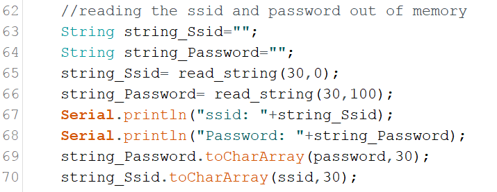
This block of code reads the WiFi routers ssid, and password out of memory. First two Strings() are declare to temporarily store the ssid, and password in. Then the function read_string(int Size,int Location) is called. You pass this function the location (in memory) of the data you want to read out of memory, and the size (in characters) of the data. It returns a String() containing the data you were looking for. Next the Strings gets converted into an Char Array. Remember that a Char Array variable had to use for the ssid and password, well here they are populate them with this command;

String.toCharArray(Char,Size) function converts a String into an Char Array. All you need is the String you want to convert, a Char Array and the size of Array. On line 69, and 70 we convert the temporary strings into the arrays that are going to be used to provide the SSID and Password credentials.
Next lets look at the read_string() function:
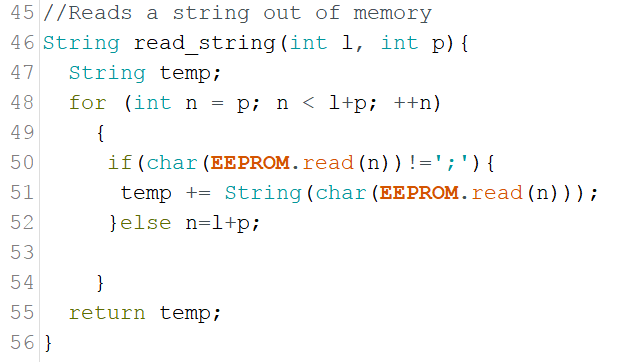
The read_string() function is strait forward. A for() loop that reads one character at a time out of memory. When it encounters the end of data string ';' character it exits the loop and returns the string as an result.
Configuring the IP information
The difficulty with configuring the IP information is that a string containing 4 groups of numbers needs to converted into 4 integers. Lets look at the code and see how it is done;
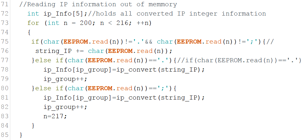
On line 73 a Array is declared of the integer type (ip_Info[5]. It can hold 5 groups of integers (The 4 from the IP, and one group for the gateway. Now remember when using Arrays, the first position always starts at 0. The ip_group variable is used to handle what IP group we are dealing with.
A simple for loop is used to read a string out of memory one character at a time. The if ()/else statement in the loop looks for the '.' and ';' characters (The '.' divides the 4 sets of IP numbers, and the';' is the end of string character) . When one of those characters is found it sends the string_IP string to the ip_convert(String) function. The ip_convert() function converts the string to an integer and returns it. The integer gets store in the ip_Info[] variable using the ip_group variable to determine what slot it gets stored in.
Lets explore the code for the ip_convert() function ;
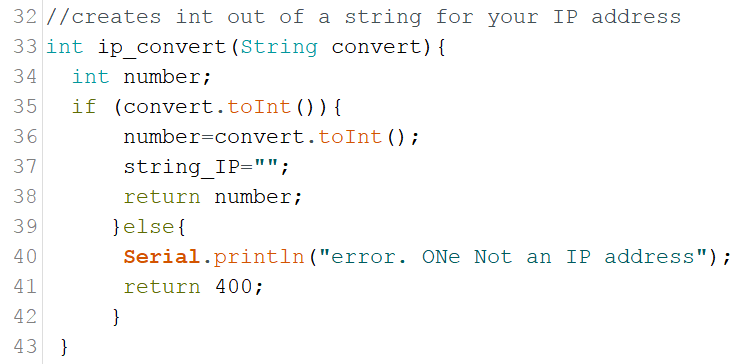
The ip_convert() function starts on line 34 of the sketch. It converts the string send to it to an integer. The syntax to convert a string into an integer is simple String.toInt(). We check if the string actually can be converted to an integer with the in statement on line 35. If it is possible to convert the string, the string_IP variable gets reset to empty and then returns the converted integer containing your IP information. If the string can't be converted to an integer it returns a value of 400 (You can use this for error checking, which I have not implemented).
Next the gateway information is read out of memory with the following code;

It uses the functions described above, saving me time and code size, and making things more streamlined :). Now it is time to put this all together and link the IP information (IP Stack) and credentials (ssid,password) to the ESP8266 and connecting it to your WiFi network. We do this with the following code;
click to enlarge
The IPAddress data type requires 4 integers divided by commas. The IP information stored in the ip_Info[] array gets use to populate the IP variables. Next we bind them to the development board using the WiFi.config() command, and it is time to connect to your WiFi router with the WiFi.begin() code.
The following code checks if the connection is working;
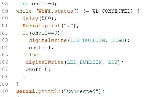
The While() loop uses the WiFi.status() function to check if it is connected. This does not check if the IP information is correct, it only checks that your credentials (ssid,password) are correct. The loop keeps cycling until it connects. I added the blinking onboard LED that blinks until connected.
Configuring the Web Server
I am not going to go deep into the webserver configuration as we have discussed it in detail in Part 1 of this tutorial. All I have done is created /on, and /off functions. The code for this can be found starting on line 113 of the sketch and the actual functions can be found starting on line 127 .
Compile this code and try to type http://insert your ip/on to turn the on board light on, and http://insert your ip/on to turn it off.
Section 3: Creating your user configurable IOT device
Download the completed sketch: complete_IOT_solution_1_0_2.ino here. I have also created a pdf with all functions in this sketch, their short descriptions and the line in the code where to find them. You can download it from here.
This is the final sketch of the tutorial. This sketch is basically WiFiAccessPoint_Write1_0.ino sketch(from Part 1), and the IOTdevice_read_Config_1_0.ino from the previous section mashed together to make one coherent sketch.
As a disclaimer I would like to say that this final sketch is not to be used without you doing thorough testing in a real world environment. I have done testing on it under controlled environment, but it has not had a monkey test done.
To make the two above mentioned sketches work I had to rework some of the variables used to deal with naming conflicts, but all the main functions and parts of the two parent sketches are there and intact.
To make the integration readable and understandable, I moved most of the code located in the setup() function of the parent sketches, and put them in their own functions (WAP(), and IOT()). I only left the shared items, like the setup of the webserver in the setup function.
The biggest change is really that I have altered the hardware configuration by adding a (spst) switch. This is basically a On and Off switch. The connection diagram can be found below. I have created the #define button_Pin 13 variable for the define the switch digital port.

I have set it up so that when the switch is in the On position you go into setup mode, and when it is Off to be in normal mode.
Another big change is part of the error checking. I have added some more comprehensive but still basic error checking with these functions:
- int ssid_error_Check(String content) on line 306
- int password_error_Check(String content) on line 321
- int ip_error_Check(String content) on line 344
- int gw_error_Check(String content) on line 382
These are very simple error check routines. They basically check if the string containing the data is the correct length, and if it contain characters that not allowed in the ssid, password, IP, and gateway. In the case of the IP I check for non alphanumeric characters with isAlpha(). This function returns a true when it contains non numeric characters. I do this with the following code:
It basically creates an error message that gets displayed in the input form if the IP address contains non Alphanumeric characters. A great place to see how to evaluate and analyse strings is this tutorial from the Arduino.cc people; link: https://www.arduino.cc/en/Tutorial/CharacterAnalysis.
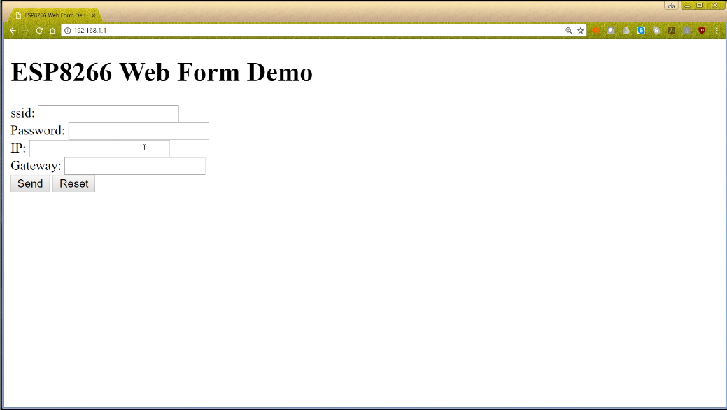
The creation of the input web form also has seen some changes. I create a function called create_form(String ssidr,String passwordr,String ipr, String gwr) (on line 218). When you call it you pass it the ssid, password, ip, and the gw address. This is done in the error checking process. If one of the error checking function return a 1 (indicating an error) the input form is returned to the web browser with previously entered values and the appropriate error message. We use the following global error messages variables (declared on line 38).
String ssid_Arg;// Error message for ssid input
String password_Arg;// Error message for password input
String ip_Arg;// Error message for ip input
String gw_Arg;// Error message for gateway input
Compile and upload the sketch and take it for a run. First set the switch into the setup configuration and type in your WiFi credentials. See how the error checking works (remember it is really basic, you might want to add some more checks to it). Then throw the switch into normal operation mode and see how it connects to your WiFi router. Go to the root / of your device with your web browser and how to turn the onboard led on and off.
This completes this tutorial. If you have further questions leave them in the comment section below and I'll try to answer them as quick as possible. I hope you enjoyed this tutorial and it increased your knowledge base so you can become a more accomplished maker.
If you like this tutorial and want to see more of this please subscribe to my periodical Newsletter by filling out the form below, or follow me on Facebook by clicking on this link, and click the Like button on my Facebook page.

Tutorial:Storing WiFi Configuration On Your ESP8266 Using The EEPROM Library Made Simple Part 1
This tutorial is part 1 of 2 that will simplify the way you can store your WiFi configuration on an ESP8266 using the EEPROM library. With this knowledge you can then build Internet Of Things (IOT) projects that can be configured by web form. This will enable to change passwords or IP configuration when needed without having to recompile your sketch.
In part 1 we learn how to write the information to your IOT project, part 2 will teach you how to read this information out of memory and configure your IOT project so it can connect to your WiFi router
| Please put some money in the tip jar by clicking on the donate button to support me so I can continue creating contend like this. P.S. please donate more than $1 as PayPal takes minimum $0.30 per transaction |

In this tutorial we are going to build an IOT device, using the ESP8266, that allows you to setup the network configuration (e.g. SSID, and password of a WiFi router ) through a form and store it in it’s memory. This is a bit harder to do then for instance using an Arduino UNO as the ESP8266 does not really have an EEPROM like all the real Arduino boards have. This is why most of us struggle to use the EEPROM library with the ESP8266 development board.
This is the first tutorial out of a 2 part series. In part 1 I will teach you how to write the data to the ESP8266. In part 2 we will teach you how to read it back out of memory to configure your IOT device to connect to your home network.
Part one has 3 sections. In section One (The EEPROM Conundrum) we will look at how to write data to the ESP8266 memory. Section Two (Setting up a basic WAP) will explain how to set up an WiFi Access Point.
"An access point is a device that creates a wireless local area network. or WLAN, usually in an office or large building. An access point sometimes connects to a wired router, switch, or hub via an Ethernet cable, and projects a Wi-Fi signal to a designated area. It is also used for users to configure IOT devices for first time use, or password changes"
In Section Three ( Adding a form to the WAP, and write data to huzzah memory ) we will put it all together to create a functional WiFi access point that writes configuration data to your ESP8266 memory
Below is a You Tube video accompanying this tutorial. For best result download the example sketches within this tutorial before watching this video.
Materials Needed in this tutorial
- The Adafruit ESP8266 Huzzah Breakout board
- 5v ftdi cable
- Access to the the SSID and password of your WiFi router you want to connect to, to get configuration data
Section One:The EEPROM Conundrum
Because many makers want to build cheap IOT solution, the ESP8266 has become a favourite to a lot of us. But writing values other than integers to its memory can be problematic. The main reason is that the standard EEPROM library does not work, because the ESP8266 does not have an EEPROM. The library we use simply emulates an EEPROM but in real life we are writing to the FLASH Memory.
Writing to the ESP8266 memory
The trick is simple; anything we write to the ESP8266 memory will have to be a string, and we can write them one character as a time. Download the sample sketch from this link:
#include <EEPROM.h> //The EEPROM libray
String string_Value;
float float_Value=111.2222;


void setup() {
string_Value=String(float_Value,4);
string_Value=string_Value+";";
EEPROM.begin(512);
for(int n=0; n< string_Value.length();n++){
  EEPROM.write(n,string_Value[n]);
}
EEPROM.commit();
}

void loop() {
  // put your main code here, to run repeatedly:

}
As you can see the code is very simple. Let me explain what we do. First we declare a String variable called string_Value and a float variable float_Value with a value of 111.2222
String string_Value;
float float_Value=111.2222;
Next in the setup() function I convert the float variable into a string. I do this using the String object. If you notice the "4" in the String(float_Value,4), this signifies the precision of the float value that gets stored in the string_Value variable. If you notice I added the "; "character to the string value.
string_Value=String(float_Value,4);
string_Value=string_Value+";";
I add the ; character as an end of string symbol. When you read data one character at a time you need to know when you have reached the end of the data. The easiest way to do this is by adding a predetermined character that symbolizes the end of data stream. I chose the ; character as you are not allowed to use them in most passwords, or URL's.
Now comes the writing process, I first initiate the EEPROM function with EEPROM.begin(512);, and I also set the size of the storage as well. Next I cycle through the string value string_Value one character at a time using a for() loop. I start writing these characters to the ESP8622 memory starting at position 0 with this command EEPROM.write(n,string_Value[n]).


"If you look at the memory we defined as a chest of drawers with 512 drawer. The first drawer has an address of 0, and the last drawer has a address of 511. As the sketch walk's through the string one character at a time, it opens the drawer with the corresponding address and deposits the character in that drawer. "
The write position in the ESP8622's memory get determined by the value n which I set to 0 in the initialization section of the for loop. I use the string.Value.length() to set how many times we go through the for loop. After the loop terminates I commit the data written to memory with EEPROM.commit()
As you see it is quite easy. You can write any value you want to the ESP8266 memory this way as long as you first convert it to a String.
Section TWO: setting up a basic WAP
Access Points are fun little things that allow you to connect to your Arduino projects to do interesting things like, get or store data that is password protected, create your own WiFi router, or for our purpose to let the user configure your project.
In this section we are setting up a basic WAP. It will allow you to give your WAP a name like a WiFi router( the SSID), require a password for authentication and security purposes, and provide you with a static IP address so you can access the web server to get information.
At the top of the sketch you see the following section near line 20 in your sketch
/* Configuration Variables for the AP name and IP. */
const char *ssid = "Test";
const char *password = "Password";
IPAddress ap_local_IP(192,168,1,1);
IPAddress ap_gateway(192,168,1,254);
IPAddress ap_subnet(255,255,255,0);
These variables set up the WAP environment. The ssid variable gives your WAP its name, and the password provides you with a password. You can change this to whatever your heart desires. Here you can also find 3 variables that define the IP information. If you understand a little bit about the IP configuration you can alter this to your liking. The IP, Gateway, and subnet get bound to the board with the following commands you can find in the setup() function roughly at line 33 in the sketch and write below it we set the name and password for the AP ;
WiFi.softAPConfig(ap_local_IP, ap_gateway, ap_subnet)
WiFi.softAP(ssid, password);
You are now ready to connect to the WAP. It still would not do anything as we have to add a service to provide. We are going to add a web-server. We do this with the following line found in your sketch on line 19;
This line adds a webserver listening on port 80. Now it is time to add some content to the webserver. We do this by adding the following lines to the setup() function near line 41.
server.on("/", handleRoot);
server.onNotFound(handleNotFound);
server.begin();
The first line tells the server to execute function handleRoot() when somebody accesses the root of the server. In our case if somebody would type http://192.168.1.1/. The next line will execute function handleNotFound() if somebody would try to access anything else other then the root of the server.
If you look at the bottom end of the sketch you actually see both functions handleRoot() and handleNotFound(). The handleRoot() function has this line of code in it;
server.send(200, "text/html", "<h1>You are connected</h1>");
This line basically sends a response to the request for data when you type http://192.168.1.1/ into your web browser and press enter. The send() function basically is made up like this; send(code,content type,content).
The code parameter is basically the type of response the webserver gives. The two most common are 200 (which means this is success full response and here is what you requested), or the 404 (which means the data requested does not exist). The next parameter is content type. For us it is plain html (text/html), and the next parameter is the actual content. In our case it is;
"<h1>You are connected</h1>"
This can also be a string variable that contains html code. If you look at the handleNotFound() function you see that we first create a string called message where we store the html response of the server not finding the requested page. Then in the send() function we give a code of 404 (page not found), a content type of text/plain, and the content is the message string.
The final component in setting up the webserver is the line server.handleClient(); in the loop() function of the sketch. The server.handleClient(); listens to the IP address provided and will call the appropriate function declared in the setup() function. Now your webserver is ready. Compile your sketch and upload it to your huzzah breakout and see what happens.
Section Three: Adding a form to the WAP, and write data to huzzah memory
In this section we combine Section one and two of this tutorial to get a WAP that writes information you enter into a form to memory. I am not going to rehash all the points explained in the previous sections, I am just going over the new stuff. Start with downloading the sketch "WiFiAccesspoint_Write1_0.ino" by clicking on this link.
The first major difference is that we create a constant char near line 17 of the sketch named INDEX_HTML. This contains the form html data that we are going to display.
The next big change you can find is near the bottom of the sketch in the handleRoot() function(on line 79 of your sketch). It has a if() statement that checks if the data received by the web server contains the input field information of the form created on line 17 of the sketch. This is done by checking for the names assigned to the input fields on the html form. See the example of an html input field below.
<input maxlength="30" name="ssid">
The following code checks if the input field name "ssid" is one of the parameters received by the webserver when you submitted it. If it did it returns a value of true, if not it returns a value of false;

The if() statement below makes sure that all field name parameters are present.

If this is true we call the handleSubmit() function. If this is not true we display the html input form.
In this sketch we don't check if the data entered is correct. If this would be a completed sketch to be used in the field it would be imperative to check this.
If the input field names exists and the if statement returns as true, we call the handleSubmit() function (on line 87 of your sketch). In this function we create an html page displaying the data the user just entered, and we call the write_to_Memory() function (on line 108 of your sketch).
We pass this function the content of each input field found in the html form. You get the content of the form input field named "ssid" with the code below;
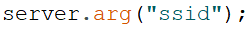
This code returns the value of the form input field as a String.
In the write_to_Memory() function the end of data symbol ";" is added to each fields data and call the write_EEPROM( ) function to write it to memory. At the end of the write_to_Memory() function we commit the data to memory using the EEPROM.commit() code.
Compile your sketch and upload it to your ESP8266. Now use a laptop or other device to connect to your WAP. If you did not change the ssid name look for the name Test in your available WiFi connection point. Use Password as the password. After it completes connecting to your IOT device start up a web browser and type 192.168.1.1 in your URL bar and press enter. A form pops up, and you are ready to type in your WiFi router credentials and press enter. Your information is now written to your ESP8266.
This completes this tutorial , check back in a week or two for Part 2 of this tutorial where we will learn how to read the data back and how to put these two sections together. If you have further questions leave them in the comments below.
If you like this tutorial and want to see more of this please subscribe to my periodical Newsletter by filling out the form below, or follow me on Facebook by clicking on this link, and click the Like button on my Facebook page.

Helpful Tip: How to create a more professional and user friendly Arduino project by storing your configuration in the EEPROM
As makers we strive to make projects that are easy to use and have a more professional feel about them. If your project is user configurable (e.g. are you using C or F for your temperature), how do you store that information so it is kept, even when the Arduino gets reset?
What if you could make your Arduino remember these types of user changeable settings (e.g. using a menu saving your Wi-Fi password)?
| Please put some money in the tip jar by clicking on the donate button to support me so I can continue creating contend like this. P.S. please donate more than $1 as PayPal takes minimum $0.30 per transaction |

As makers we strive to make projects that are easy to use and have a more professional feel about them. If your project is user configurable (e.g. are you using C or F for your temperature), how do you store that information so it is kept, even when the Arduino gets reset?
What if you could make your Arduino remember these types of user changeable settings (e.g. using a menu saving your Wi-Fi password)? The solution is using the EEPROM library. This library allows you to store your configuration data like your WIFI router name and password, and be able to change it if you get a new router or password. The drawback is that you can only write and erase data 100,000 times so be careful to only write the most important data. Luckily you can read this data as many times as you want without any issue.
To write your data you use the; EEPROM.write(address, value), and to read your data you use the EEPROM.read(address). The drawback is that writing anything other than an integer can be complicated.
In the next weeks, I will be writing a tutorial on how to write your configuration or other information to your Arduino/Compatible so you too can create professional looking projects.If you are interested subscribe to my periodical Newsletter by filling out the form below, or follow me on Facebook by clicking on this link, and click the follow button.