

Project: Creating A NodeMCU Data-Logger Using The Cloud
In this sample project we are going to build a NodeMCU data logger that uses the Adafruit cloud to store the temperature and humidity data. To make it even more exciting we are putting the NodeMCU to sleep in the periods that we are not transmitting the data to the cloud.
| Please put some money in the tip jar by clicking on the donate button to support me so I can continue creating contend like this. P.S. please donate more than $1 as PayPal takes minimum $0.30 per transaction |
In this project we are going to build a NodeMCU data logger that uses the Adafruit cloud to store the temperature and humidity data. To make it even more exciting we are putting the NodeMCU to sleep in the periods that we are not transmitting the data to the cloud.
The basics of this project are as follows. First we are going to connect a Temperature Humidity sensor (The DHT11 or DHT22) to the NodeMCU. After getting that to work we are going to setup a feed on the Adafruit IO cloud. Then we will write the code to send the temperature data to the cloud using the MQTT protocol. Finally we add the sleep function of the ESP8266 to the mix.
This sounds like a lot, but you will actually see it is a very simple and straightforward process. If you look back a couple of weeks I build the same datalogger only using the Arduino Pro Mini, a RTC, and an SD card writer/reader breakout board. For this project we will only require A NodeMCU, a DHT11/22 sensor, and a connection to the interweb.
Index
List Of Materials Needed For This Project

Connecting the DHT11/22 Sensor
To connect the DHT11/22 family of sensors we are going to use a library specifically designed for the ESP8266 micro controller or compatibles. The library is called DHTesp.h and needs to be installed using the Arduino IDE Library manager.
You can find the Library Manager under the Sketch menu and selecting the Include Libraries, and then the Manage Libraries option. In the search bar type dht to only show the libraries related to the DHT11/22 sensor. Click the more info link on the DHT library for the ESPx. A dropdown will appear where you select the latest version of the driver, then click the install button.
Click To Enlarge
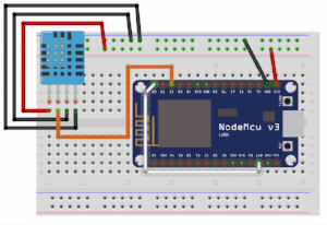
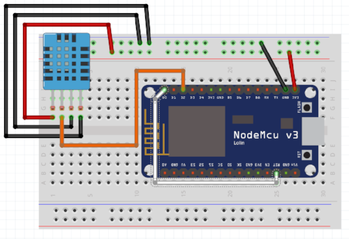
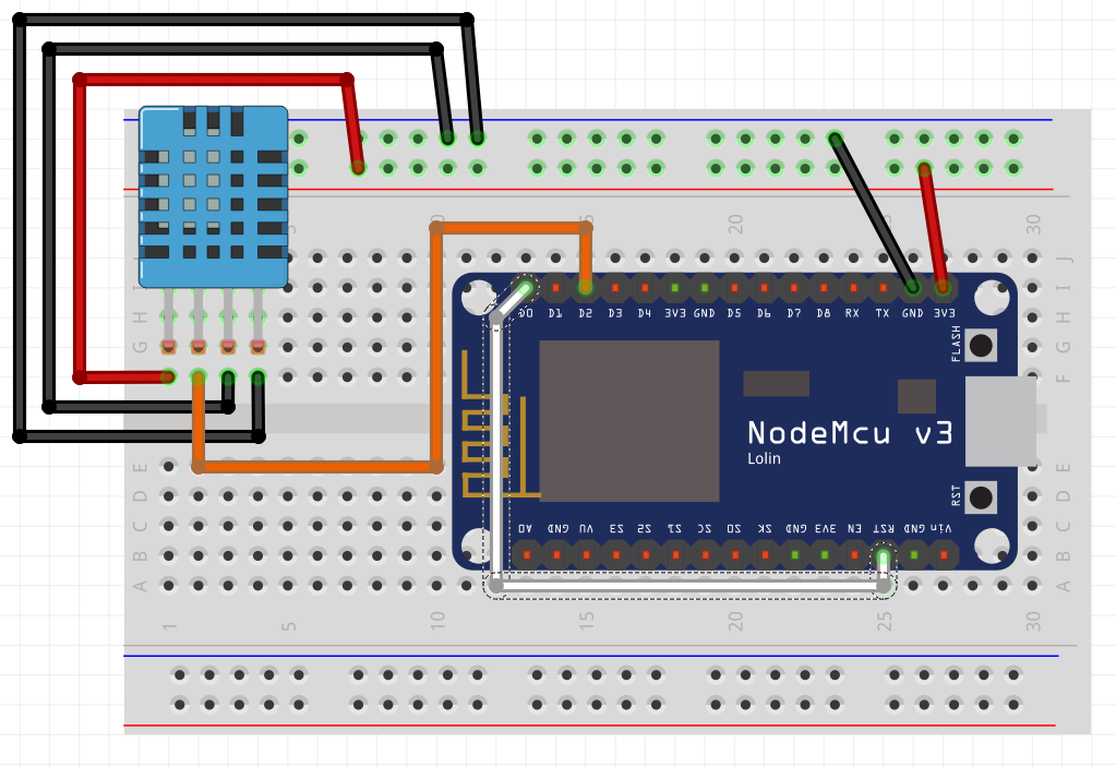
I selected this library as it takes in consideration the slow communication speed of the DHT11/22 when running on 3.3v. Next we connect the sensor as follows (with the grid facing you)
| DHT 11/22 | NodeMCU | Arduino equivalant |
| Pin 1 VCC In | 3.3V | 3.3V |
| Data Out | Pin D2 | Digital Pin 4 |
| GND | GND | GND |
| GND | GND | GND |
| Please put some money in the tip jar by clicking on the donate button to support me so I can continue creating contend like this. P.S. please donate more than $1 as PayPal takes minimum $0.30 per transaction |
If you like this sample project and want to see more of this type of content, consider putting some money in the tip jar by clicking the Donate button. If you want to see more of this content subscribe to my newsletter with the form below or follow me on Facebook. This link will take you to my Facebook page. Hope to see you soon, have a great day and bye for now

Project: Example using a RTC to wake-up an Arduino Data Logger
This project is to give a practical example of using power save modes with Arduino's. It uses a Real Time Clock (RTC) to wake up an Arduino Data Logger. It write the temperature and humidity in a room to a micro SD card. It is optimized for saving power thus can run of a battery pack.
| Please put some money in the tip jar by clicking on the donate button to support me so I can continue creating contend like this. P.S. please donate more than $1 as PayPal takes minimum $0.30 per transaction |

This blog is an example project to explain how to use an Real Time Clock (RTC) module as a mechanism to wake up an Arduino we put to sleep. The code and explanation for putting an Arduino to sleep, and how to wake it up again can be found in this tutorial: A Guide To Putting Your Arduino To Sleep . For you to understand this project I strongly recommend you read this guide first as the code in this project is based upon the code explained in that tutorial.
Index
- The Project overview
- List of Materials needed for this project
- Downloads
- Connecting the Adafruit RTC 3231 breakout board
- The Code for the Adafruit 3231 RTC Breakout board
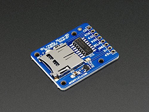
- Connecting the Adafruit Micro SD Breakout Board
- The code for the Adafruit Micro SD Breakout board
- Connecting the Humidity/ Temperature Sensor DHT11/DHT22
- The Code for the DHT11/DHT22
- Power/Current Consumption (mA)
The Project overview
The purpose of this project is to create a data logger that logs temperature/humidity data on an sd card. The data that gets logged has a date and time stamp. This project will run off a battery pack, thus we put the Arduino to sleep when no data is being logged.
In this project I am using the Adafruit DS3231 RTC breakout board. I used this particular one because of it has a SQW pin, and it uses two Analog pins for communication. In most projects the Analog pins are not used so the RTC does not take up valuable digital pins.
The other feature of this RTC is that you can set alarms that get activated without the need to communicate with the Arduino board (Your Arduino can be asleep and the alarm will still fire). When the alarm fires it pulls the SQW pin to low. We use that action to fire the Interrupt attached to digital pin 2 to wake up an sleeping Arduino, as explained in the turorial (A Guide To Putting Your Arduino To Sleep).
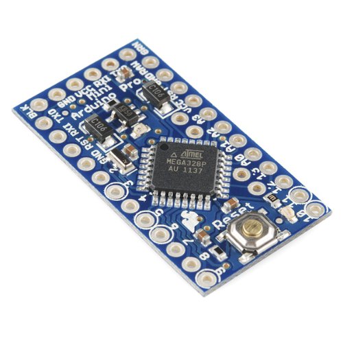
Arduino Pro Mini side view to show how to solder in pin A4 and A5
We use the DHT11/22 sensor to read the temperature and humidity of a specific room, and the Adafruit micro SD breakout board to write the data to an SD card. The Arduino used is the Arduino Pro Mini. When soldering the header pins also put header pins pointing upwards in the A4 and A5 holes. We will be using these to communicate with the RTC breakout board
List of Materials needed for this project
Note: This is the first project where I will be using links to Amazon products to list what products are needed. I do this just to recover the costs of the components I use. I don't sell any of these items, but will receive a very small commission. Please consider using these links to buy your products to support me creating these projects/tutorials.

Downloads
The next list has all items needed to be downloaded for this project. It is recomended to do this before you continue onwards to download all files.
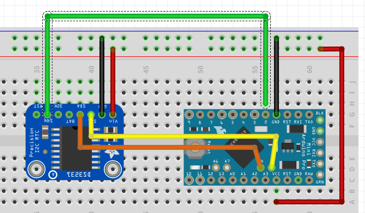
Connecting the Adafruit RTC 3231 breakout board
Lets look at how to connect the RTC to your Arduino Pro Mini:

| DS3231 RTC PINS | Arduino/Breadboard Pins |
| 5V | breadboard 5V |
| GND | breadboard GND |
| SCL | Arduino A5 |
| SDA | Arduino A4 |
| SQW | Arduino D2 |

| SD Breakout PINS | Arduino/Breadboard Pins |
| 5V | breadboard 5V |
| GND | breadboard GND |
| CLK | Arduino D13 |
| DO | Arduino D12 |
| DI | Arduino D11 |
| CS | Arduino D10 |
This image shows you what it would look like on your breadboard
The code for the Adafruit Micro SD Breakout board
The code for this breakout is easy to understand and strait forward. First we load the libraries

The libraries used are part of the Arduino IDE so no need to download anything special here. Next we declare the global variables needed for this board.

First we declare the File name object named myFile, than we declare a constant int (chipSelect). This variable sets the digital pin needed for the Adafruit breakout board. Don't change it, Adafruit wants it to be that pin so we are stuck with it like this.
The actual writing to and reading from a file is done in a function called writeData().
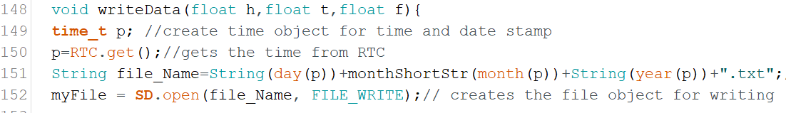
If you remember that this whole sketch is to log temperature and humidity data onto an sd memory card. In this function we do the actual writing. We send this function 3 arguments; float h (humidity), float t (temperature in Celsius), and float f (temperature in Fahrenheit ).
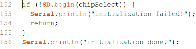
On line 149 we declare another time variable named p, and get the current date and time from the RTC on line 150. We do this for 2 reasons. Reason one is to create a filename that is today's date. This way it is easy to see when data was logged, and reason two is that we use the current time as a time stamp to know exactly when the data was logged.
On line 151 we create a string called file_Name. The string contains today's date. We use the time/date variable to do so. On line 152 we use the string to open, or create a file with the file_Name variable content as name with the SD.open() function. Lets look a bit closer at the syntax of this function.
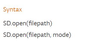
The filepath is the path to the file including the filename. The mode is either FILE_READ to read from a file, or FILE_WRITE to append to a file. If you use the FILE_WRITE with a filename that does not exist it will create the file name. If you use the SD.open(filepath) it will automatically assume you want to read from the file. If you want to see all option click on the following link; https://www.arduino.cc/en/Reference/SDopen
The SD.open() action gets stored in the myfile object created in the declaration section. Now we have the file open and are ready to write to it.
Click to Enlarge
The if(myFile) statement checks if the file exist and is in the correct format. If this statement returns a false it will print an error message to the Serial Monitor. The most common reason for this is that the sd card is not formatted correctly or not in its socket, or you used a filename that contains characters that are not allowed.
Note: The Adafruit breakout board requires a specific format. For more information on this go to the following link: https://learn.adafruit.com/adafruit-micro-sd-breakout-board-card-tutorial/formatting-notes
On line 158 we actually write to the file. We use the same format used to print a line to the serial monitor, but instead of using Serial, we use the file object myFile. After we wrote to the file we close it with the myFile.close(); line. It is very important that we close the file after reading or writing to it. If the file is not closed correctly it will be corrupted and you won't be able to write to or open that file again.
Connecting the Humidity/ Temperature Sensor DHT11/DHT22
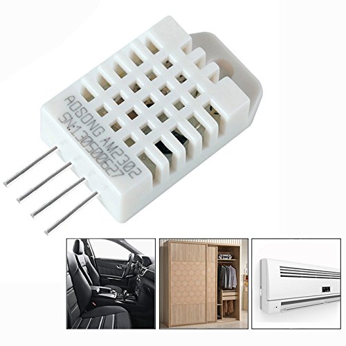
The pinout of this sensor is done with the sensor front grid facing you:
| DHT11/22 | Arduino/Breadboard Pins |
| 5V | breadboard 5V |
| Data out | Arduino D4 |
| GND | breadboard GND |
| GND | breadboard GND |
The image shows all components on the breadboard.
The Code for the DHT11/DHT22
In my sketch you will see the code for the DHT11 as I have this sensor in my collection of sensors, but if I had to use this project in a real world scenario I would use the DHT22 as it has greater precision.
We are using the Adafruit library. You are right this project is definitely Adafruit centric. No I am not getting paid by Adafruit, but if LadyAda is listening I can always use some cash. But enough with the useless banter as you are here to learn something. Lets look at the declaration section for this sensor;
First we load the library

Next we are creating the object to communicate to the sensor and some global variables we need to create the object;

On line 27 we declare the variable that tells the sensor what digital pin we communicate with. We use digital pin 4.
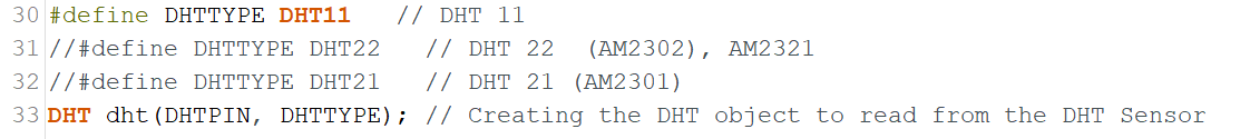
As I explained I am using the DHT11, but if you use the DHT22 comment out line 30 and un-comment line 31. Next we create the dht object on line33. We use the DHTTYPE variable to let the object know what sensor we using, and the DHTPIN variable to let it know what pin to communicate with.
In the setup() function we use the following statement to start communication with the sensor;

The actual reading from the sensor is done in function temp_Humi(). This function is called from line 107 from the Going_To_Sleep() function.
Click To Enlarge
In this function we read the Humidity % with the dht.readHumidity() function, and the temperature both in Celsius dht.readTemperature() and Fahrenheit dht.readTemperature(true). We store these in float variables (h for humidity,t for temperature in Celsius, and f for temperature in Fahrenheit). We take these float values and pass them to the writeData() function where they are written to the SD card.
Power/Current Consumption (mA)
After we tested the code and see how the project runs using the FTDI cable it is time to connect it to an external power supply and a multimeter. We do this to measure how much current we draw. If you are not sure how to do this, check out my tutorial: How to measure power consumption and why should to do it.
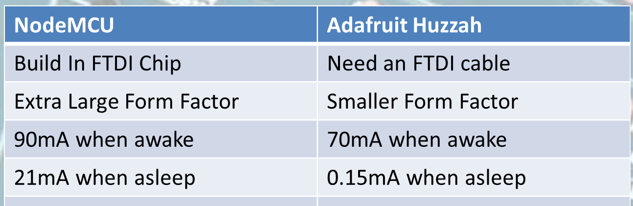
After hooking up the project with an external power supply and multimeter we see it consumes 24-28mA when awake and a small 100th of a second spike of 100mA as we write to the SD card. When it is sleeping it only uses 10mA. We can actually save a couple of more milliAmps out of the circuit if we were able to turn the power off on the SD breakout board. Actually we save almost 7mA ending up with only a use of 3mA when it is asleep.
We do this by using an NPN transistor as a switch to turn the power off on the SD breakout board when the Arduino is asleep.
Note: When you put the Arduino to sleep all the components are still drawing a base current. If we can turn off the power on these components we lower the current/power consumption even more.
This a bit advanced so I won't go in to details how an NPN Transistor works, but I will explain how to implement it. Checkout the image below to see what the diagram looks like.
Hardware alteration
Using the 2N2222/MPS2222A transistor, we connect a 1K resistor to the middle leg of the transistor, connect the other end of the resistor to D9 on the Arduino. By putting pin D9 high we turn the switch on, and by putting pin D9 low we turn the switch Off. Next we connect the right leg of the transistor (with the flat part facing you) to the 5V on the bread board and connect the left leg to the 5V in on the SD breakout board.
Note: You might ask why don't we do this for all the components to save even more. Some components need to have power as they need to do things while the Arduino sleep e.g. the RTC needs to wake up the Arduino, and some components take time to start working when power is applied to them e.g. the Humidity/Temperature Sensor. This you find out through trial and error.
Code alterations:
You can download the completed power saver version of the sketch from here

On line 39 we add the following line to declare the pin we use to turn the power on and off on the SD breakout board. Next we make digital pin 9 an out put pin and turn it high with the following code
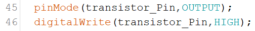
We add these lines in the setup() function on line 45 and 46. Then in the Going_To_Sleep() function we pull digital pin to low to turn of the power to the SD breakout board just before we put the Arduino asleep with this line of code. We put it on line 101

After the Arduino is woken up we add a line of code that will pull pin 9 back to high on line 109 before we call the temp_Humi() function.

Finally we have to reinitialize the SD breakout because we powered it down. We do this in the writeData() function. We do this before we declare the time object with these lines of code;
Making these alterations to your project make it even more energy efficient.
In Closing
This is a practical application that shows when putting your Arduino to sleep really can have practical applications. This project can run on 4 C cell batteries for approximately 3 to 4 weeks. If you run it without the sleep mode you only get 4 to 7 days out of it.
If you like this project and would like to see more of the same type, please subscribe to my newsletter using the form below or like and follow my Facebook page. This way you get notified when a new post is available. If you have questions or suggestions please email at akurk@thearduinomakerman.info me or leave it in the comments below. Have a great day and see you next time.

Project: IOT Christmas Lights Display
A couple of year’s back I bought one of the Neopixel light strings from Adafruit. I think it was 200 leds. I used them one season and put them away. This Christmas I decided to make an IOT Christmas light display out of it just above our horizontal blinds.
To do this I used the code explained in the Tutorial:Storing WiFi Configuration On Your ESP8266 Using The EEPROM Library Made Simple Part 1 and Tutorial part 2. I also used code from the Adafruit Neopixel example code and integrated it with my base code to create an IOT device from the tutorial.
| Please put some money in the tip jar by clicking on the donate button to support me so I can continue creating contend like this. P.S. please donate more than $1 as PayPal takes minimum $0.30 per transaction |
A couple of year’s back I bought one of the Neopixel light strings from Adafruit. I think it was 200 leds. I used them one season and put them away. This Christmas I decided to make an IOT Christmas light display out it.
To do this I used the code explained in the Tutorial:Storing WiFi Configuration On Your ESP8266 Using The EEPROM Library Made Simple Part 1 and Tutorial part 2 as my base code. I also used code from the Adafruit Neopixel example code and integrated it with my base code. The complete IOT Christmas Light Display code can be downloaded from this link.
I won’t explain the base code again as I have a great tutorial that already does this. I will just explain the steps I took adding the Neopixel code and how to control them
I split this project into the steps I tackled to integrate the Neopickel code into the IOT code. You can download the complete sketch here.
INDEX
- STEP 1 CREATE THE COLOURSET() FUNCTION
- STEP 2 CALLING THE COLOURSET() FUNCTION
- STEP 3 CREATING THE WEB INPUT SCREEN
- STEP 4 THE HANDLEROOT() FUNCTION
- STEP 5 MAKE SURE THAT THE LIBRARIES ARE INSTALLED
- STEP 6 THE HARDWARE SETUP
Here is a list of the hardware I chose to use:
- Huzzah ESP8266 Breakout
- 8-channel Bi-directional Logic Level Converter - TXB0108 from Adafruit
- On/Off toggle switch
- 10K Resistor
- 5V FTDI cable
- WS2812 Addressable Light String (200 LED)
- 5V 2A power supply (depending on how many lights the Amperage will vary )
Step 1 Create the colourset() function
This function sets the light string colour. I started with copying this code from the Adafruit example sketch. For an explanation of this code go to the Adafruit tutorial that explains it in detail. But here are the highlights.
When calling the colourset() function you pass it the RGB value of the colour you want the led’s to turn. In the for() loop you see the NUMPIXELS variable. It has been set on line 61 and contains the number of LED’s your lightstring contains.
void colourset(int r,int g,int b){
  for(int i=0;i<NUMPIXELS;i++){
      // pixels.Color takes RGB values, from 0,0,0 up to 255,255,255
          pixels.setPixelColor(i, pixels.Color(r,g,b)); // sets the colour
          pixels.show(); // This sends the updated pixel color to the hardware.
          colour=0;
       }
}
Step 2 calling the colourset() function
This is done in a Switch()/case statement on line 217 in the loop() function. It uses a int variable colour (yes this is the correct spelling in Canada) that gets set through a web form. If you look at option 4 in the case statement you see a bunch of code. This code randomly changes the colours of the string creating a rainbow affect.
  switch(colour){
    case 0:

    break;
    case 1:
    colourset(255,0,0);//Red
    break;
    case 2:
    colourset(0,255,0);//Green
    break;
    case 3:
    colourset(244,229,66);//yellow
    break;
    case 4:
     uint16_t i, j;
      breakon=0;
      Serial.println("rainbow");
      for(j=0; j<256*5; j++) { // 5 cycles of all colors on wheel
        for(i=0; i< pixels.numPixels(); i++) {
          pixels.setPixelColor(i, Wheel(((i * 256 / pixels.numPixels()) + j) & 255));
          server.handleClient();
          if(breakon==1){
            Serial.println("breakon");
            Serial.println("Colour: "+ String(colour));
            breakon=0;
            j=256*5+1;
            i=pixels.numPixels()+1;

          }
        }
        server.handleClient();
        if(breakon==1){
            Serial.println("breakon");
            Serial.println("Colour: "+ String(colour));
            breakon=0;
            j=256*5+1;
            i=pixels.numPixels()+1;

          }
        pixels.show();
        delay(50);
      }
      //colour=0;

    break;
    case 5:
    colourset(32,58,229);//blue
    break;
    case 6:
    colourset(204,11,229);//purple
    break;
    case 7:
    colourset(r_Arg,g_Arg,b_Arg);
    break;
    case 8:
    colourset(0,0,0);//off
    break;
  }
}
For a better understanding of this rainbow code, look in the Adafruit tutorial for the Neopixels. I modified the code a bit. The reason for this is that it uses 2 nested for() loops that make it hard to communicate with the microcontroller. If you remember that the web server uses this function server.handleClient() to read request from the server.
As long as your sketch is in a for() loop the request won’t be honored. This is why I created a variable called breakon. If it has a value of 1 the if() statements I have added to the code will terminate the for() loops and will allow the microcontroller to fulfill the web requests. The value of the breakon variable gets set to 1 in the handleroot() function on line 309 when a server request is made. It gets set back to 0 in the switch()/case statement in the loop() function

Step 3 Creating the web input screen
The web input screen html code is setup in function colour_form() starting on line 371 . It contains several forms nested in a table structure. It is a normal form that when you press the button makes a request to the root of your server and sending a hidden field with an integer that corresponds with the colour you want to set.
<input type=\"hidden\" name=\"colour\" value=\"1\">"
The value of this hidden field gets used to set the colour variable.
colour=server.arg("colour").toInt();
The colour variable then gets used to operate the Switch()/case statement in the loop() function.
Step 4 The handleroot() function
In this function we use the server.Arg(“colour”) value to set the colour variable. It also sets the breakon variable to 1 so we can exit out of the for() loops in the rainbow mode. You can find the code on line 319
      }else if (server.hasArg("colour")){
        Serial.println("Colour is set to: "+server.arg("colour"));
        colour=server.arg("colour").toInt();
        breakon=1;
      }
It also reads the RGB value from the web form option to create your own colour. The code can be found on line 311
      if(server.hasArg("RED") && server.hasArg("GREEN")&& server.hasArg("BLUE")){
         Serial.println("RGB");
        colour=server.arg("ssid").toInt();
        r_Arg=server.arg("RED").toInt();
        g_Arg=server.arg("GREEN").toInt();
        b_Arg=server.arg("BLUE").toInt();
       breakon=1;

      }else if (server.hasArg("colour")){
Step 5 make sure that the libraries are installed
The final steps are to make sure you copy the #include <Adafruit_NeoPixel.h> library and the appropriate variables needed to run this library
- #define PIN 12// sets the digital pin to send the data to
- #define NUMPIXELS 200 //number of led’s on your light strings
- Adafruit_NeoPixel pixels = Adafruit_NeoPixel(NUMPIXELS, PIN, NEO_GRB + NEO_KHZ800); //sets up the light string
Step 6 The hardware setup
Click To Enlarge
Setup switch
It’s explained in the IOT tutorials. We have connected it to Digital pin 13.
LED Light string
The LED light string is addressable, using the WS2812 LED. It uses a 5v logic and the ESP8266 uses 3.3v logic. This is why we used the Adafruit TXB0108 logic level. I used this one because it is easy to use, and I had one laying around. But what the logic level does is convert the 3.3v logic info send from the Huzzah and converts it to 5v so the LED string can operate. We use digital pin 12 on the Huzzah for this. Look at the schematic above how it has been connected.
Another thing to think about is an appropriate power supply. Each of those led’s can draw up to 55mA. All the details about this can be found in the Adafruit tutorial.
If you have any questions leave them in the comments and I get back to you as soon as possible. If you like this project and would like to see more of it you can subscribe to my news letter using the form below.
Tutorial on creating graphics for the Nokia 5110 LCD using an Arduino and the Adafruit library
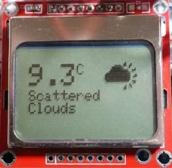
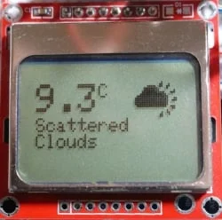
Creating graphics for the Nokia 5110 display using an Arduino and the Adafruit Library
I use the Nokia 5110 display in many of my projects. It is inexpensive and reliable. I also use the Adafruit library for this display as it is easy to use and feature rich. The only issue I had with this library was displaying icons and other graphics on it.
All the tutorials I could find dealt with how to concert a bitmap to a format this display could use were with a utility called LCD Assistant. And this does not work with the Adafruit library. This tutorial will take you through the steps how to create graphics using the Adafruit Library
| Please put some money in the tip jar by clicking on the donate button to support me so I can continue creating contend like this. P.S. please donate more than $1 as PayPal takes minimum $0.30 per transaction |
I use the Nokia 5110 display in many of my projects. It is inexpensive and reliable. I also use the Adafruit library for this display as it is easy to use and feature rich. The only issue I had with this library was displaying icons and other graphics on it.
All the tutorials I could find dealt with how to concert a bitmap to a format this display could use were with a utility called LCD Assistant. And this does not work with the Adafruit library. This is for one single reason, it outputs in hex where the Adafruit library uses a binary format.
After searching for a while I found a utility called Bitmap encoder. Watch the tutorial I have created which will take you through the process of taking an image and converting it into a bitmap you can display on the Nokia 5110 lcd.
- Link to Bitmap encoder utility: https://github.com/Rodot/BitmapEncoder
- Link to Adafruit Tutorial for the Nokia 5110 display: https://learn.adafruit.com/nokia-5110-3310-monochrome-lcd
- Link to the Adafruit Library: https://learn.adafruit.com/nokia-5110-3310-monochrome-lcd/downloads