

Project: Creating A NodeMCU Data-Logger Using The Cloud
In this sample project we are going to build a NodeMCU data logger that uses the Adafruit cloud to store the temperature and humidity data. To make it even more exciting we are putting the NodeMCU to sleep in the periods that we are not transmitting the data to the cloud.
| Please put some money in the tip jar by clicking on the donate button to support me so I can continue creating contend like this. P.S. please donate more than $1 as PayPal takes minimum $0.30 per transaction |
In this project we are going to build a NodeMCU data logger that uses the Adafruit cloud to store the temperature and humidity data. To make it even more exciting we are putting the NodeMCU to sleep in the periods that we are not transmitting the data to the cloud.
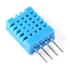
The basics of this project are as follows. First we are going to connect a Temperature Humidity sensor (The DHT11 or DHT22) to the NodeMCU. After getting that to work we are going to setup a feed on the Adafruit IO cloud. Then we will write the code to send the temperature data to the cloud using the MQTT protocol. Finally we add the sleep function of the ESP8266 to the mix.
This sounds like a lot, but you will actually see it is a very simple and straightforward process. If you look back a couple of weeks I build the same datalogger only using the Arduino Pro Mini, a RTC, and an SD card writer/reader breakout board. For this project we will only require A NodeMCU, a DHT11/22 sensor, and a connection to the interweb.
Index
List Of Materials Needed For This Project


Connecting the DHT11/22 Sensor
To connect the DHT11/22 family of sensors we are going to use a library specifically designed for the ESP8266 micro controller or compatibles. The library is called DHTesp.h and needs to be installed using the Arduino IDE Library manager.
You can find the Library Manager under the Sketch menu and selecting the Include Libraries, and then the Manage Libraries option. In the search bar type dht to only show the libraries related to the DHT11/22 sensor. Click the more info link on the DHT library for the ESPx. A dropdown will appear where you select the latest version of the driver, then click the install button.
Click To Enlarge
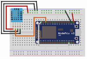
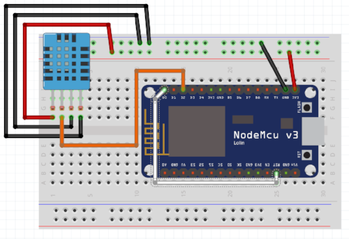
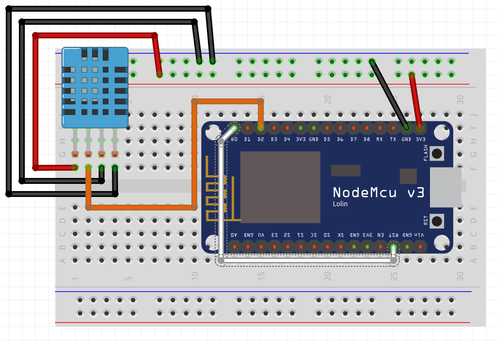
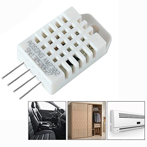
I selected this library as it takes in consideration the slow communication speed of the DHT11/22 when running on 3.3v. Next we connect the sensor as follows (with the grid facing you)
| DHT 11/22 | NodeMCU | Arduino equivalant | ||||
| Pin 1 VCC In | 3.3V | 3.3V | ||||
| Data Out | Pin D2 | Digital Pin 4 | ||||
| GND | GND | GND | ||||
| GND | GND | GND |
| Please put some money in the tip jar by clicking on the donate button to support me so I can continue creating contend like this. P.S. please donate more than $1 as PayPal takes minimum $0.30 per transaction |
If you like this sample project and want to see more of this type of content, consider putting some money in the tip jar by clicking the Donate button. If you want to see more of this content subscribe to my newsletter with the form below or follow me on Facebook. This link will take you to my Facebook page. Hope to see you soon, have a great day and bye for now

Tutorial: Intro to the NodeMCU
This tutorial is a simple guide to get started with the NodeMCU one of the most popular forms of the ESP8266 on the market right now. The NodeMCU is a powerful board that is good on the pocket book, but has its drawbacks. We are going to explore how to set this board up with the Arduino IDE, and some other simple tips and trick to get you started.
| Please put some money in the tip jar by clicking on the donate button to support me so I can continue creating contend like this. P.S. please donate more than $1 as PayPal takes minimum $0.30 per transaction |
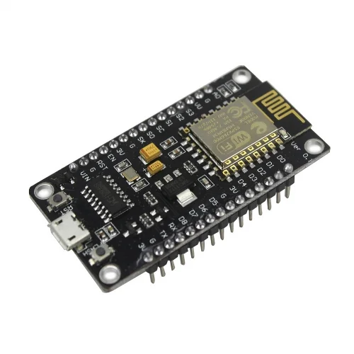
This tutorial is a simple guide to get started with the NodeMCU one of the most popular forms of the ESP8266 on the market right now. The NodeMCU is a powerful board that is good on the pocket book, but has its drawbacks. We are going to explore how to set this board up with the Arduino IDE, and some other simple tips and trick to get you started.
Material Needed For This Tutorial


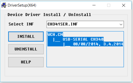
Driver Installation
One of the drawbacks of this board is that you have to install a usb drivers to communicate with this board. You can download the driver from here. Before you try to install the driver be sure you have Administrator privileges on your computer.
After you have downloaded the driver installation package, and you have Administrator privileges you can start the installation. Use a Micro USB Type-B cable that is rated for data transfer. Follow these steps to install your Driver
- Download Driver
- Connect your NodeMCU to your computer using the USB cable.
- Run the driver installation package you downloaded as Administrator
- Click the install button
The driver should install without any problems. The main issue that people have is either not connecting the NodeMCU to the computer before starting the install, or not having the right cable, or not having the correct privileges on your computer. If your driver install fails first make sure all the above mentioned requirements have been met. If it still doesn’t work you have entered the realm of unsupported freeware, and sadly are on a journey of exploration that can be painful. I have not seen it fail when all the requirements have been met.
Preparing the Arduino IDE
If you have never worked with an ESP8266 type of board you need to install the drivers and libraries for this in your Arduino IDE. . The people at Sparkfun have a nice tutorial for this. You go there by clicking on this link: https://learn.sparkfun.com/tutorials/esp8266-thing-hookup-guide/installing-the-esp8266-arduino-addon
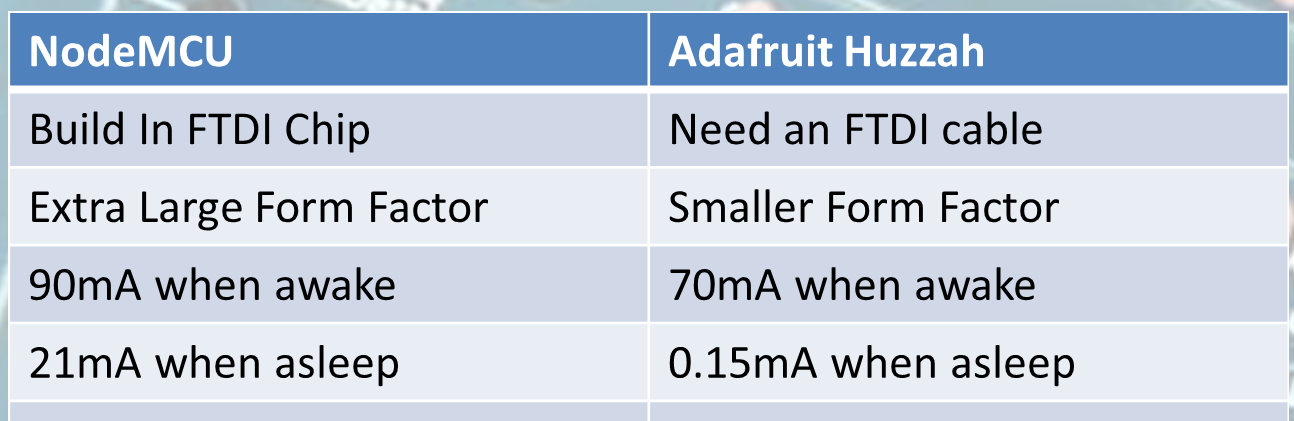
The NodeMCU form factor
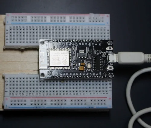
You might have noticed by now that the NodeMCU is a bit large. It won’t fit on a regular size breadboard (well it does but you have no room to connect anything to it). What I have done to make it fit is use a dremel tool and cut a normal breadboard in two along the spine (See picture) Now it will fit perfectly.
Pinouts
This is one of the greatest drawbacks of the NodeMCU for beginner users. The labels on the NodeMCU don’t correspond to the digital pins (GPIO pins) we know and love when working with Arduino compatibles. You need image ? to make sense of it.
For example pin D1 on the board corresponds with GPIO 5 (Digital pin 5 on your Arduino). The best thing to do is keep that image handy as a guide to find out what pin does what, and how they correspond to the Arduino world.
Specs
The board runs at 3.3v, and all pins can have a max load of 12mA and a 3.3v logic. When buying breakout boards or other components make sure they run on those specs. It also means you have to be careful when using the pins from the NodeMCU to power components. 12mA is not a lot and this makes it easy for you to overload a pin and fry your board. The board also has only one analog port A0, and it is for input only (like all other ESP8266).
You can power the board with an external power supply no greater than 12V. The documentation is spars, but what I have found is that it can handle 20V but the volt regulator will get dangerously hot. This is why I recommend having a power supply that supplies no more than 12V.
Onboard LED
Often we use an onboard LED in the development phase to error check. This board does not have the LED connected to pin/gpio13, instead it has it connected on pin/gpio 2.
Uploading a Sketch
Next we are going to upload the blink sketch to the NodeMCU. If you have followed the above steps you should have installed the hardware driver (driver name) and the Arduino IDE drivers and libraries we are ready to upload a blink sketch.
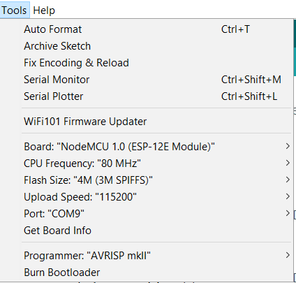
Configuration for the NodeMCU
We start by selecting the NodeMCU 1.0 (ESP-12 Module) under the board options in the Tools menu (See Image for the complete configuration). See Image ? . The only thing that could be different on your computer is the COM port. You just need to select the COM port available to you under the Tools menu Port option.
Below you find the sample sketch to make the onboard LED flash on the NodeMCU
int LED_PIN= 2;

void setup() {
  // initialize digital pin LED_BUILTIN as an output.
  pinMode(LED_PIN, OUTPUT);
}

// the loop function runs over and over again forever
void loop() {
  digitalWrite(LED_PIN, HIGH);   // turn the LED on (HIGH is the voltage level)
  delay(1000);                       // wait for a second
  digitalWrite(LED_PIN, LOW);    // turn the LED off by making the voltage LOW
  delay(1000);                       // wait for a second
}
In Closing
Check back in about 14 days when I build a more elaborate project with the NodeMCU to see what you can do with this board. But for now if you enjoyed this tutorial please subscribe to my newsletter by filling out the form below, or go to my Facebook page by clicking on the link and follow and like the page. By doing his you will get an alert every time I post a new article. If you have questions or suggestions please email at akurk@thearduinomakerman.info me or leave it in the comments below. Have a great day and see you next time.

Tips: How to ask for help
There is no shame in asking for help when you get stuck on your Arduino projects, but there are definitely right and wrong ways to ask for help. Often people are not sure what information needs to be displayed. Here are some simple tips on how to ask a question, and how to trouble shoot to be able to get the information needed for a question
| Please put some money in the tip jar by clicking on the donate button to support me so I can continue creating contend like this. P.S. please donate more than $1 as PayPal takes minimum $0.30 per transaction |

As you can imagine I often get emails with questions and cries for help. I actually enjoy these emails and try to help as much as I can. One of the issues I see is that some makers don’t know how to formulate a question to get the help they need. Just the other day I got an email from somebody who asked about a project I posted on Instructables a long time ago.
The project is for an oxygen analyzer to analyze dive tanks. The question was “ I get this weird error when I put sensor of make x on your sketch, what is wrong”? The problem with this question is it does not contain any information to find out what is happening. People are not able to help you if you don’t provide the correct information. If you ask this in a public forum people are not going to respond to your question.
Before you ask your question you have to do your due diligence. Below are some steps you have to take first before you ask for help.
What information do you need to supply?
You are asking for help, and may I add at no cost, you need to make it as easy as possible for people to help you. For example the person asking me about the oxygen analyzer should minimally have supplied what the error was and what changes he had made to the sketch.
If it is a question about a sample sketch that returns an error, you minimally need to supply what OS you are compiling on, the version of the Arduino IDE you use, and what libraries you are using, and of course the error message in as much detail as possible. If you made alterations to the supply code give an explanation on what changes were made.
Minimal List of information you should supply
- Sample sketch
- Libraries used
- Arduino IDE Version
- What hardware used (Arduino related)
- OS version you compiling on (If it is a compiler error)
Before asking for help first find out what is wrong
Before asking for help you need to try to figure out for yourself what the issue is. By doing this you also have a better understanding of the problem. It will also help you to understand the answers you are going to receive. Here are some tips on doing your own trouble shooting before asking for help.
Trouble with your hardware
First make sure your hardware is working. You do this by testing each component separately. If you create a temperature/humidity data logger that uses a sd card breakout board, make sure that each component functions alone with your Arduino. First make a sample sketch with the temperature/ humidity sensor and see if you get the data you are expecting, and do the same with the sd card breakout.
I do this for all my projects. I first test each sub component separately before combining them. This way I know I wired everything correctly and know that is not the issue. If everything seems to work separately, and it stops working when combined all the components you know there is a conflict. Find out what components are conflicting by testing them with only an Arduino and two components at a time.
Note:In the beginning try to use components and breakout boards from the big guys like; Adafruit, Sparkfun, Pololu, Seeedstudio. They always have tutorials on how to use their components, and forums you can ask questions in.
Now you have done your homework, and are ready to ask people for help. First create a diagram with something like fritzing to give a visual representation of how the components are connected. Supply the sample sketch you made to work with these components, and give as much info about the versions, makes, and models of your hardware. By doing this you will get better quality of help, and avoid the trolls making nasty comments when you ask for help.
Note: A sample sketch is a sketch that only contains the code needed to show the problem. It is a fully working sketch, but paired down just to reveal what the problem is. It is a good way to trouble shoot, and to provide enough code to people to see what the problem is
Use your serial monitor to debug
The programmers among us know a bit about debugging and how important it is. Normally you can add breakpoints (a spot the program halts so you can look at the values of variables) to see what is happening, but because this is not possible with an Arduino we use the Serial.println() function to debug your sketch. This is often done because your project is not responding as you thought it would be. When I write a sketch it is always full of these Serial.println() statements to see what is happening. I normally remove them from the final sketch as it looks cluttery (if that’s a word).
For instance you press a button and your Arduino is not responding to it’s request. By simply seeing if your digital pin is high or low you can see if the button press has an effect, or maybe your if() statement is looking for the wrong answer. A simple Serial.println(digitalRead()) will let you know if the digital pin in question is HIGH or LOW. Look at the following example where I put lines in for debugging:
  buttonState = digitalRead(buttonPin);
  //Next lines are fo debugging
  Serial.print("buttonState: ");
  Serial.println(buttonState);
  // check if the pushbutton is pressed. If it is, the buttonState is HIGH:
  if (buttonState == HIGH) {
    // turn LED on:
    digitalWrite(ledPin, HIGH);
  } else {
    // turn LED off:
    digitalWrite(ledPin, LOW);
  }
This is often done in situations where complex calculations are in play using many different variable types e.g doubles, floats, and integers. By seeing what the actual value of these variables are before going into the calculation you can often find the problem.
Language Reference
Another common issue is when you are not sure what function to use or how to convert a data type. Before reaching out to someone, try going to the Arduino Language Reference page. This is an amazing resource with tons of information. This is my go to place when I am not sure what function to use, or what is the correct syntax.
Look here first and get an idea of what you want to use in your sketch and how to use it. Sometimes the information in this area is a bit thin and their examples could be better. If you get stuck and not sure how to get unstuck, that’s when you reach out to the community. First try to come up with an example sketch how you think it needs to go, and then post your question on your favourite place.
Sometimes just except the answer even if you don’t completely understand it
Sometimes the answer will be in the form of a cryptic piece of code that works for you but doesn’t make sense to you. Just run with it and try to figure out what part you don’t understand and google it. Most of the time (and it happens to me to) it is currently out of your scope of knowledge and will take a lot of reading, learning, and gaining more experience to understand it. As long as you know what part you don’t understand how to communicate with that code you can implement it in your code as a form of a black box (a black box is something you provide data to, it gives you the answer, but you have no clue how).
In Closing
If you implement all of my recommendations, 80% of the time you will find your own answers. The 20% where you will need help, you will look like somebody that wants help and shows that you have worked for it. It also gives the person answering your question an understanding of your experience level. Just saying “I am a noob” does not help when asking your question. If the correct information is not provided, people can’t help you.
Don’t be afraid to ask for help, but in the end you get out of it what you put into it. Don’t be embarrassed if you are not sure if what you did was right, if you show you want to learn there are many people out there who want to help you. Finally be proud of your accomplishments, and stand behind your work, even if you are not sure you are correct. We all started off as a noob and had to learn and gain experience by asking the community for help.
If you like this project and would like to see more of the same type, please subscribe to my newsletter using the form below or like and follow my Facebook page. This way you get notified when a new post is available. If you have questions or suggestions please email at akurk@thearduinomakerman.info me or leave it in the comments below. Have a great day and see you next time.

Project: Example using a RTC to wake-up an Arduino Data Logger
This project is to give a practical example of using power save modes with Arduino's. It uses a Real Time Clock (RTC) to wake up an Arduino Data Logger. It write the temperature and humidity in a room to a micro SD card. It is optimized for saving power thus can run of a battery pack.
| Please put some money in the tip jar by clicking on the donate button to support me so I can continue creating contend like this. P.S. please donate more than $1 as PayPal takes minimum $0.30 per transaction |

This blog is an example project to explain how to use an Real Time Clock (RTC) module as a mechanism to wake up an Arduino we put to sleep. The code and explanation for putting an Arduino to sleep, and how to wake it up again can be found in this tutorial: A Guide To Putting Your Arduino To Sleep . For you to understand this project I strongly recommend you read this guide first as the code in this project is based upon the code explained in that tutorial.
Index
- The Project overview
- List of Materials needed for this project
- Downloads
- Connecting the Adafruit RTC 3231 breakout board
- The Code for the Adafruit 3231 RTC Breakout board
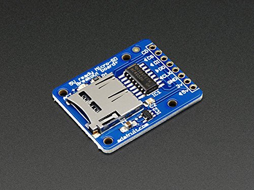
- Connecting the Adafruit Micro SD Breakout Board
- The code for the Adafruit Micro SD Breakout board
- Connecting the Humidity/ Temperature Sensor DHT11/DHT22
- The Code for the DHT11/DHT22
- Power/Current Consumption (mA)
The Project overview
The purpose of this project is to create a data logger that logs temperature/humidity data on an sd card. The data that gets logged has a date and time stamp. This project will run off a battery pack, thus we put the Arduino to sleep when no data is being logged.
In this project I am using the Adafruit DS3231 RTC breakout board. I used this particular one because of it has a SQW pin, and it uses two Analog pins for communication. In most projects the Analog pins are not used so the RTC does not take up valuable digital pins.
The other feature of this RTC is that you can set alarms that get activated without the need to communicate with the Arduino board (Your Arduino can be asleep and the alarm will still fire). When the alarm fires it pulls the SQW pin to low. We use that action to fire the Interrupt attached to digital pin 2 to wake up an sleeping Arduino, as explained in the turorial (A Guide To Putting Your Arduino To Sleep).
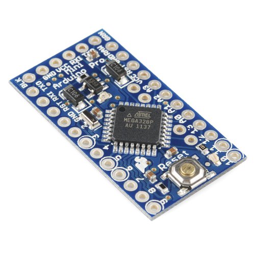
Arduino Pro Mini side view to show how to solder in pin A4 and A5
We use the DHT11/22 sensor to read the temperature and humidity of a specific room, and the Adafruit micro SD breakout board to write the data to an SD card. The Arduino used is the Arduino Pro Mini. When soldering the header pins also put header pins pointing upwards in the A4 and A5 holes. We will be using these to communicate with the RTC breakout board
List of Materials needed for this project
Note: This is the first project where I will be using links to Amazon products to list what products are needed. I do this just to recover the costs of the components I use. I don't sell any of these items, but will receive a very small commission. Please consider using these links to buy your products to support me creating these projects/tutorials.

Downloads
The next list has all items needed to be downloaded for this project. It is recomended to do this before you continue onwards to download all files.
Connecting the Adafruit RTC 3231 breakout board
Lets look at how to connect the RTC to your Arduino Pro Mini:

| DS3231 RTC PINS | Arduino/Breadboard Pins | |||||
| 5V | breadboard 5V | |||||
| GND | breadboard GND | |||||
| SCL | Arduino A5 | |||||
| SDA | Arduino A4 | |||||
| SQW | Arduino D2 |

| SD Breakout PINS | Arduino/Breadboard Pins |
| 5V | breadboard 5V |
| GND | breadboard GND |
| CLK | Arduino D13 |
| DO | Arduino D12 |
| DI | Arduino D11 |
| CS | Arduino D10 |
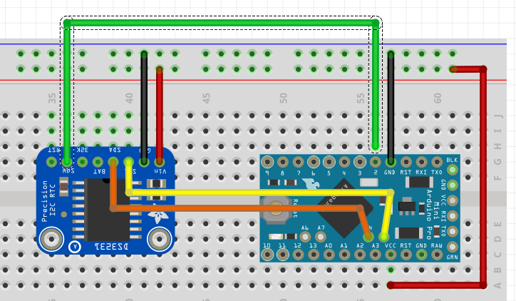
This image shows you what it would look like on your breadboard
The code for the Adafruit Micro SD Breakout board
The code for this breakout is easy to understand and strait forward. First we load the libraries

The libraries used are part of the Arduino IDE so no need to download anything special here. Next we declare the global variables needed for this board.

First we declare the File name object named myFile, than we declare a constant int (chipSelect). This variable sets the digital pin needed for the Adafruit breakout board. Don't change it, Adafruit wants it to be that pin so we are stuck with it like this.
The actual writing to and reading from a file is done in a function called writeData().
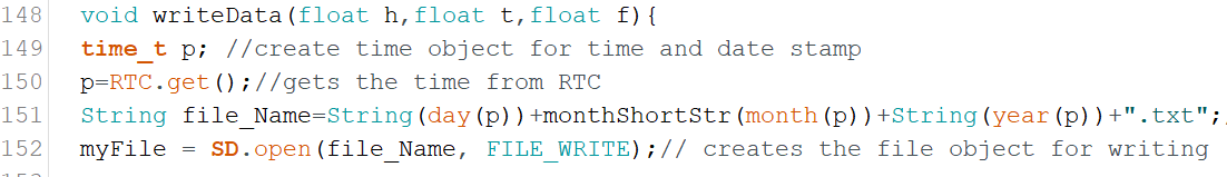
If you remember that this whole sketch is to log temperature and humidity data onto an sd memory card. In this function we do the actual writing. We send this function 3 arguments; float h (humidity), float t (temperature in Celsius), and float f (temperature in Fahrenheit ).
On line 149 we declare another time variable named p, and get the current date and time from the RTC on line 150. We do this for 2 reasons. Reason one is to create a filename that is today's date. This way it is easy to see when data was logged, and reason two is that we use the current time as a time stamp to know exactly when the data was logged.
On line 151 we create a string called file_Name. The string contains today's date. We use the time/date variable to do so. On line 152 we use the string to open, or create a file with the file_Name variable content as name with the SD.open() function. Lets look a bit closer at the syntax of this function.
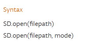
The filepath is the path to the file including the filename. The mode is either FILE_READ to read from a file, or FILE_WRITE to append to a file. If you use the FILE_WRITE with a filename that does not exist it will create the file name. If you use the SD.open(filepath) it will automatically assume you want to read from the file. If you want to see all option click on the following link; https://www.arduino.cc/en/Reference/SDopen
The SD.open() action gets stored in the myfile object created in the declaration section. Now we have the file open and are ready to write to it.
Click to Enlarge
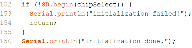
The if(myFile) statement checks if the file exist and is in the correct format. If this statement returns a false it will print an error message to the Serial Monitor. The most common reason for this is that the sd card is not formatted correctly or not in its socket, or you used a filename that contains characters that are not allowed.
Note: The Adafruit breakout board requires a specific format. For more information on this go to the following link: https://learn.adafruit.com/adafruit-micro-sd-breakout-board-card-tutorial/formatting-notes
On line 158 we actually write to the file. We use the same format used to print a line to the serial monitor, but instead of using Serial, we use the file object myFile. After we wrote to the file we close it with the myFile.close(); line. It is very important that we close the file after reading or writing to it. If the file is not closed correctly it will be corrupted and you won't be able to write to or open that file again.
Connecting the Humidity/ Temperature Sensor DHT11/DHT22
The pinout of this sensor is done with the sensor front grid facing you:
| DHT11/22 | Arduino/Breadboard Pins |
| 5V | breadboard 5V |
| Data out | Arduino D4 |
| GND | breadboard GND |
| GND | breadboard GND |
The image shows all components on the breadboard.
The Code for the DHT11/DHT22
In my sketch you will see the code for the DHT11 as I have this sensor in my collection of sensors, but if I had to use this project in a real world scenario I would use the DHT22 as it has greater precision.
We are using the Adafruit library. You are right this project is definitely Adafruit centric. No I am not getting paid by Adafruit, but if LadyAda is listening I can always use some cash. But enough with the useless banter as you are here to learn something. Lets look at the declaration section for this sensor;
First we load the library

Next we are creating the object to communicate to the sensor and some global variables we need to create the object;

On line 27 we declare the variable that tells the sensor what digital pin we communicate with. We use digital pin 4.
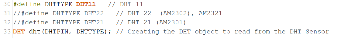
As I explained I am using the DHT11, but if you use the DHT22 comment out line 30 and un-comment line 31. Next we create the dht object on line33. We use the DHTTYPE variable to let the object know what sensor we using, and the DHTPIN variable to let it know what pin to communicate with.
In the setup() function we use the following statement to start communication with the sensor;

The actual reading from the sensor is done in function temp_Humi(). This function is called from line 107 from the Going_To_Sleep() function.
Click To Enlarge
In this function we read the Humidity % with the dht.readHumidity() function, and the temperature both in Celsius dht.readTemperature() and Fahrenheit dht.readTemperature(true). We store these in float variables (h for humidity,t for temperature in Celsius, and f for temperature in Fahrenheit). We take these float values and pass them to the writeData() function where they are written to the SD card.
Power/Current Consumption (mA)
After we tested the code and see how the project runs using the FTDI cable it is time to connect it to an external power supply and a multimeter. We do this to measure how much current we draw. If you are not sure how to do this, check out my tutorial: How to measure power consumption and why should to do it.
After hooking up the project with an external power supply and multimeter we see it consumes 24-28mA when awake and a small 100th of a second spike of 100mA as we write to the SD card. When it is sleeping it only uses 10mA. We can actually save a couple of more milliAmps out of the circuit if we were able to turn the power off on the SD breakout board. Actually we save almost 7mA ending up with only a use of 3mA when it is asleep.
We do this by using an NPN transistor as a switch to turn the power off on the SD breakout board when the Arduino is asleep.
Note: When you put the Arduino to sleep all the components are still drawing a base current. If we can turn off the power on these components we lower the current/power consumption even more.
This a bit advanced so I won't go in to details how an NPN Transistor works, but I will explain how to implement it. Checkout the image below to see what the diagram looks like.
Hardware alteration
Using the 2N2222/MPS2222A transistor, we connect a 1K resistor to the middle leg of the transistor, connect the other end of the resistor to D9 on the Arduino. By putting pin D9 high we turn the switch on, and by putting pin D9 low we turn the switch Off. Next we connect the right leg of the transistor (with the flat part facing you) to the 5V on the bread board and connect the left leg to the 5V in on the SD breakout board.
Note: You might ask why don't we do this for all the components to save even more. Some components need to have power as they need to do things while the Arduino sleep e.g. the RTC needs to wake up the Arduino, and some components take time to start working when power is applied to them e.g. the Humidity/Temperature Sensor. This you find out through trial and error.
Code alterations:
You can download the completed power saver version of the sketch from here

On line 39 we add the following line to declare the pin we use to turn the power on and off on the SD breakout board. Next we make digital pin 9 an out put pin and turn it high with the following code
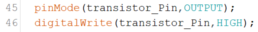
We add these lines in the setup() function on line 45 and 46. Then in the Going_To_Sleep() function we pull digital pin to low to turn of the power to the SD breakout board just before we put the Arduino asleep with this line of code. We put it on line 101

After the Arduino is woken up we add a line of code that will pull pin 9 back to high on line 109 before we call the temp_Humi() function.

Finally we have to reinitialize the SD breakout because we powered it down. We do this in the writeData() function. We do this before we declare the time object with these lines of code;
Making these alterations to your project make it even more energy efficient.
In Closing
This is a practical application that shows when putting your Arduino to sleep really can have practical applications. This project can run on 4 C cell batteries for approximately 3 to 4 weeks. If you run it without the sleep mode you only get 4 to 7 days out of it.
If you like this project and would like to see more of the same type, please subscribe to my newsletter using the form below or like and follow my Facebook page. This way you get notified when a new post is available. If you have questions or suggestions please email at akurk@thearduinomakerman.info me or leave it in the comments below. Have a great day and see you next time.

Tutorial:A guide to putting your Arduino to sleep
Tutorial:A guide to putting your Arduino to sleep
If you need to run your Arduino of a battery pack, you need to find a way to reduce it's power consumption. One of the the best ways to do this is putting your Arduino to sleep when it is not performing any tasks. This tutorial is a great place to start on learning how to put your Arduino to sleep.
| Please put some money in the tip jar by clicking on the donate button to support me so I can continue creating contend like this. P.S. please donate more than $1 as PayPal takes minimum $0.30 per transaction |

Sometimes we are in a situation that requires us to put an Arduino in a place where plugging it in to the power grid is not an option. This happens often when we try to log information in a remote site, or only need to have your Arduino active at a specific interval/action.
In these cases putting your Arduino to sleep is the perfect thing to do. Their attention is only required for a short amount of time e.g. log data in a specific interval, or put out an alert when a predetermined event happens. In this tutorial we are going to experiment with putting your Arduino to sleep and see how to turn your Arduino back on.
This tutorial familiarizes you with the concept and has a small exercise to see what it takes to put an Arduino to sleep. In the next couple of blog posts (in 2 weeks or so) I will show post a couple a projects that will show you how to wake your Arduino using a sensor, or a Real Time Clock module (RTC).
MATERIALS NEEDED IN THIS TUTORIAL


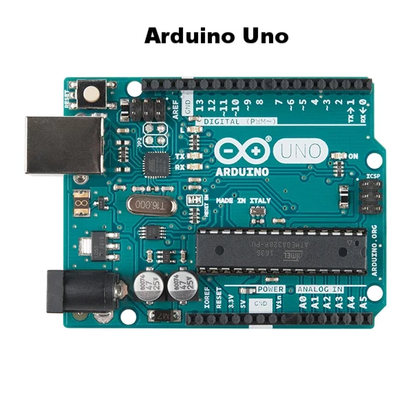
What board to use?
In this tutorial we will be using the Arduino Uno just because it is an easier board to prototype on. In a real live project I would use an Arduino Pro Mini for this. The Arduino Uno and the Arduino Pro Mini have very similar characteristics, the Arduino pro mini has a lot less hardware to power (e.g. the USB portion, extra leds, and some other stuff) thus using a lot less power. This is the reason why the Arduino Pro mini is a better choice.
To give an example a Uno uses between 30-40 mA when awake and about 19 mA when asleep. The Pro Mini uses 25mA when awake and 0.57 mA when asleep. As every mA matters when hooking it up to a battery you can see that there is no contest and the Arduino Pro Mini is the winner.
Note: As a beginner Maker the Arduino Pro Mini might be a bit intimidating, but there is no reason for it. Yes you need to solder the headers onto the board, and you need a FTDI cable to upload your sketch, but other than that there are no major differences.
Sleep mode
When you look at the documentation of the ATmega328p (click this link for a copy of this document) processor used for both Arduino Uno and the Arduino Pro mini you notice there are many different sleep modes available. But in a real world scenario there is really only one mode that is useful; The Power down mode (SLEEP_MODE_PWR_DOWN).
When you put your Arduino to sleep it turns off all unnecessary components, reducing the power consumption of the MCU (Microcontroller Unit). In this mode the only way you can wake it up is the use of an external influence (e.g. we give it a nudge to wake up). We will examine how to do this a bit later in this tutorial.
Interrupts
Before we go into the code to put an Arduino to sleep we need to understand the interrupt concept. The best way to describe it is ; You are working on something you really need to concentrate on. You wear headphones blasting your music loud to drown out your surrowndings . You are so concentrated on this that the outside world is lost to you. The only way to get your attention is by giving you a nudge. After you receive this nudge you pay attention to what the interruption is about, and after dealing with it you put the music back on and continue with your task.
Note: I am not going to go to deep into what interrupts are good for, but if you want to learn more about this concept check out my tutorial (Using Interrupts to improve the functionality of your project) on this topic
Most true Arduino’s have a couple of pins that do just that. The Uno and the Pro Mini have 2 pins (d2 and d3) that have the capability to interrupt what the Arduino is doing. With this we can nudge the Arduino back to a waking state.
Putting your Arduino To Sleep
You can download the code for this section for here.
Let’s look at the code for this section
Image_1 click to enlarge
Image 1 contains the code snippet that loads the library that contains everything we need to put your Arduino to sleep, We also declare the variable interruptPin for digital pin 2. We will later use this for making pin 2 an input pin. Next we will look at the Setup() function.

Image_2 Click To Enlarge
Image 2 has the code for the Setup() function. It is all straight forward. We declare digital pin 13 as an output pin (LED_BUILTIN is a build in variable for digital pin 13 where an onboard led is connected to). We are using the LED as an indecator for when the Arduino is asleep (when LED is on Arduino is awake, when off the Arduino is asleep).
On line 18 we set digital pin 2 as an input pin. You notice we use INPUT_PULLUP instead of INPUT. By doing this we use the build-in pull-up resistor to prevent the pin from flopping between HIGH and LOW when nothing is attached to it (same thing you would do with a button).
Next we are going to the main loop() function;
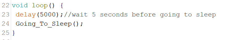
Image_3
On line 23 we put in a delay of 5 seconds before we call the Going_To_Sleep() function on line 24. This is just so you can see that the onboard LED is on to show your Arduino is awake, and the moment we call this the Going_To_Sleep() function the LED goes off to indecate the Arduino is asleep.
Next lets look at the Going_To_Sleep() function itself;
Image_4 Click To Enlagre
On line 28 we call the sleep_enable() function which is part of the avr/sleep.h library. It enables us to put the Arduino to sleep, without calling it we can't put the Arduino to sleep. On line 29 we attach an interrupt to pin 2 as I explained in the Interrupt section.
Syntax
attachInterrupt (interrupt, ISR, mode);
As you notice we use a 0 to indicate that we are using pin 2. This is because the Arduino Uno/Pro Mini have 2 interrupts. Interrupt 0 is connected to digital pin 2, and Interrupt 1 is connected to digital pin 2. The ISR is the function name that is called when the interrupt is called. In our case it is called wakeUp. The mode is what needs to happen to the digital pin to call the interrupt. In our case the pin needs to be pulled LOW (to GND).
On line 30 we set the set of sleep mode we want. In our case it goes and shuts down everything it can. On line 31 we turn off the LED, and on line 32 we wait a second to give the board the time to turn the led off. Next we actually put the Arduino to sleep with the sleep_cpu() function.
The code halts here until the interrupt is called. After waking up the Arduino will first execute the code in the wakeUp() function and then will continue with line 34 printing the wakeup message on the serial monitor, and on line 35 turning the LED back on.
Image_5
In the wakeUp() function we print a line to the serial monitor to let you now the interrupt has been called. The next two lines are very important to make sure we do not get an unintentional loop where the sketch can get stuck, and making your project fail.
On line 40 we disable the sleep function, and on line 41 we detach the interrupt from pin 2. As I said we do this to prevent a possible endless loop situation.
Exercise 1
Step 1)
Now it is time to upload the sketch. But before doing that put a jumper wire in d2. Just leave it unplugged on the other end for now. Load your sketch and wait 5 seconds for the LED to turn off and the Arduino to go to sleep.
Step 2)
After the LED turns off insert the other end of the jumper wire in a GND pin on your Arduino Uno. This will pull pin 2 LOW triggering the interrupt, thus awaking the sleeping Arduino. After the LED comes back on you can remove the jumper wire out of GND and 5 seconds later the Arduino goes back to sleep.
IN CLOSING
Now you know the principles of what it takes to put your Arduino to sleep. As you see it is a very simple process. Finding a good mechanism to control this project is sometimes a bid more problematic. For this reason I will post a couple example projects on how to wake up an Arduino using a sencor (e.g. motion sensor), and a Real Time Clock module (RTC) that will be designed so you can use them and integrate that into your own project.
If you like this tutorial and would like to see more of the same type, please subscribe to my newsletter using the form below or like my Facebook page. This way you get notified when a new post is available. If you have questions or suggestions please email me or leave it in the comments below. Have a great day and see you next time.

Tutorial: How to measure current consumption and why should you do it?
A lot of makers don't know how important it is to know the current draw of your project, or why you need to know this. In this tutorial I will explain to you how to measure the current draw of your project, and why it is so important to know this.
I often get asked the question of what type of power supply to use for projects. Most of us know the voltage required, but how much current it draws and why you need to know this is a mystery to many beginner makers. To start with what is this current thing? "In comes the analogy that uses the flow of water to explain these things".
| Please put some money in the tip jar by clicking on the donate button to support me so I can continue creating contend like this. P.S. please donate more than $1 as PayPal takes minimum $0.30 per transaction |
A lot of makers don't know how important it is to know the current draw of your project, or why you need to know this. In this tutorial I will explain to you how to measure the current draw of your project, and why it is so important to know this.
I often get asked the question of what type of power supply to use for projects. Most of us know the voltage required, but how much current it draws and why you need to know this is a mystery to many beginner makers. To start with what is this current thing? "In comes the analogy that uses the flow of water to explain these things".
Let’s say that a battery that we use to power our project is a bucket of water with a hose attached to it. The water pressure at the end of the hose is what we consider the voltage. The speed the water runs through the hose is the current and that is measured in Amps.
Yes this never made sense to me either. It comes down to this if your project consumes more current then your power supply has to offer it won’t run, and can even damage your power supply. We measure current in Amperes or Amps for short (Symbol used is A).
One way to roughly figure out what power supply to use is by reading the documentation of all the components used in your project, and see their current draw (how much Amp(A) or milliamp(mA)). Add these numbers up and you roughly know what the amperage your power supply needs to be.
Note of caution: If you use your laptop USB to power your project you could damage your USB port if the current draw is too high. This is why it is a good practice to have an external power supply to power your project, even when you have a USB cable connected to your Arduino.
MATERIALS NEEDED IN THIS TUTORIAL


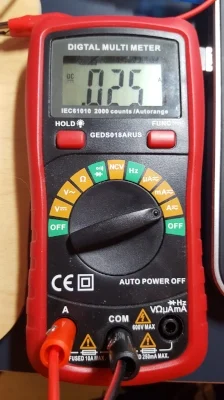
The other way to find out the current draw is by using a multimeter. Follow the these steps to setup your multimeter for this exercise:

Step 1) Look at the bottom of your multimeter you will notice 3 or 4 ports where you plug your probes in to. The black probe plugs into the COM port (COM stands for common ground). The red probe for this exercise should be plugged into the port with the A symbol (or 10A or something similar).
Note of caution: Multimeters have a limit on how much Amperage a port they can handle. Most likely your multimeter also has a port that measures the current in mA. I normally don’t use this one as it is so easy to damage if you don’t watch it, and you still get enough precision through the A port.

Step 2) Turn the dial of your multimeter to A and use the DC mode. Some multimeters will have multiple A options on the dial. We are using DC (direct current), look for an A with this symbol behind it .
Click To Enlarge
Step 3) Next using the adapter we connect the red probe from your multimeter to the plus (+) terminal of your power supply. Connect the black probe to the Vin on your Arduino Uno. Finally connect the GND on your Arduino Uno to your power supply minus (-) terminal. This is called putting your multimeter in in series, or in line with your power supply.
Figure 1
Your setup should look a little like figure 1. You should now see how much current your project requires.
Note: Some components require a start-up current (DC motors are bad for this). Your multimeter might not be fast enough to register this, and might not notice this if the power supply can handle this. This happened to me when I started using my desktop power supply. I had a DC motor that needed 3A current to start, after it was running the current use dropped back to under 1A.
Another good reason for knowing how much current your project uses is when you try to run it of a battery pack. Most USB battery packs are graded (the Capacity ) in milliamp hours (mAh). To figure out how long it will last all you need to know is its capacity and how much current your project draws. All you have to do nexts is following this simple formula:
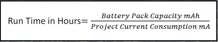
Divide the battery pack capacity in mAh by the projects current draw in mA. If you have a battery back that provides 16750mAh and your project consumes 32 mA just divide 16750mAh by 32mA

With a battery pack with a capacity of 16750mAh and a project consuming 32mA has a runtime of about 523 hours. Just a disclaimer; this is not precise in anyway. Environmental factors like temperature have a big impact on the actual run time. Another factor is the quality of the power cells used in your battery pack. All battery packs will start to discharge quicker as it loses charge, some might also have voltage drop. So the moral of this story is that you have to run a test to see the actual run time, the calculation will give you a proximate value only.
In Closing
Knowing your projects current consumption can make sure you get the right power supply for your project, reducing the chance of power supply failure or unexplained freeze ups of your project. It can also help you figure out what battery pack you need for your project.
If you like this tutorial and would like to see more of the same type, please subscribe to my newsletter using the form below or like my Facebook page. This way you get notified when a new post is available. If you have questions or suggestions please email me or leave it in the comments below. Have a great day and see you next time.

Project: IOT Christmas Lights Display
A couple of year’s back I bought one of the Neopixel light strings from Adafruit. I think it was 200 leds. I used them one season and put them away. This Christmas I decided to make an IOT Christmas light display out of it just above our horizontal blinds.
To do this I used the code explained in the Tutorial:Storing WiFi Configuration On Your ESP8266 Using The EEPROM Library Made Simple Part 1 and Tutorial part 2. I also used code from the Adafruit Neopixel example code and integrated it with my base code to create an IOT device from the tutorial.
| Please put some money in the tip jar by clicking on the donate button to support me so I can continue creating contend like this. P.S. please donate more than $1 as PayPal takes minimum $0.30 per transaction |
A couple of year’s back I bought one of the Neopixel light strings from Adafruit. I think it was 200 leds. I used them one season and put them away. This Christmas I decided to make an IOT Christmas light display out it.
To do this I used the code explained in the Tutorial:Storing WiFi Configuration On Your ESP8266 Using The EEPROM Library Made Simple Part 1 and Tutorial part 2 as my base code. I also used code from the Adafruit Neopixel example code and integrated it with my base code. The complete IOT Christmas Light Display code can be downloaded from this link.
I won’t explain the base code again as I have a great tutorial that already does this. I will just explain the steps I took adding the Neopixel code and how to control them
I split this project into the steps I tackled to integrate the Neopickel code into the IOT code. You can download the complete sketch here.
INDEX
- STEP 1 CREATE THE COLOURSET() FUNCTION
- STEP 2 CALLING THE COLOURSET() FUNCTION
- STEP 3 CREATING THE WEB INPUT SCREEN
- STEP 4 THE HANDLEROOT() FUNCTION
- STEP 5 MAKE SURE THAT THE LIBRARIES ARE INSTALLED
- STEP 6 THE HARDWARE SETUP
Here is a list of the hardware I chose to use:
- Huzzah ESP8266 Breakout
- 8-channel Bi-directional Logic Level Converter - TXB0108 from Adafruit
- On/Off toggle switch
- 10K Resistor
- 5V FTDI cable
- WS2812 Addressable Light String (200 LED)
- 5V 2A power supply (depending on how many lights the Amperage will vary )
Step 1 Create the colourset() function
This function sets the light string colour. I started with copying this code from the Adafruit example sketch. For an explanation of this code go to the Adafruit tutorial that explains it in detail. But here are the highlights.
When calling the colourset() function you pass it the RGB value of the colour you want the led’s to turn. In the for() loop you see the NUMPIXELS variable. It has been set on line 61 and contains the number of LED’s your lightstring contains.
void colourset(int r,int g,int b){
  for(int i=0;i<NUMPIXELS;i++){
      // pixels.Color takes RGB values, from 0,0,0 up to 255,255,255
          pixels.setPixelColor(i, pixels.Color(r,g,b)); // sets the colour
          pixels.show(); // This sends the updated pixel color to the hardware.
          colour=0;
       }
}
Step 2 calling the colourset() function
This is done in a Switch()/case statement on line 217 in the loop() function. It uses a int variable colour (yes this is the correct spelling in Canada) that gets set through a web form. If you look at option 4 in the case statement you see a bunch of code. This code randomly changes the colours of the string creating a rainbow affect.
  switch(colour){
    case 0:

    break;
    case 1:
    colourset(255,0,0);//Red
    break;
    case 2:
    colourset(0,255,0);//Green
    break;
    case 3:
    colourset(244,229,66);//yellow
    break;
    case 4:
     uint16_t i, j;
      breakon=0;
      Serial.println("rainbow");
      for(j=0; j<256*5; j++) { // 5 cycles of all colors on wheel
        for(i=0; i< pixels.numPixels(); i++) {
          pixels.setPixelColor(i, Wheel(((i * 256 / pixels.numPixels()) + j) & 255));
          server.handleClient();
          if(breakon==1){
            Serial.println("breakon");
            Serial.println("Colour: "+ String(colour));
            breakon=0;
            j=256*5+1;
            i=pixels.numPixels()+1;

          }
        }
        server.handleClient();
        if(breakon==1){
            Serial.println("breakon");
            Serial.println("Colour: "+ String(colour));
            breakon=0;
            j=256*5+1;
            i=pixels.numPixels()+1;

          }
        pixels.show();
        delay(50);
      }
      //colour=0;

    break;
    case 5:
    colourset(32,58,229);//blue
    break;
    case 6:
    colourset(204,11,229);//purple
    break;
    case 7:
    colourset(r_Arg,g_Arg,b_Arg);
    break;
    case 8:
    colourset(0,0,0);//off
    break;
  }
}
For a better understanding of this rainbow code, look in the Adafruit tutorial for the Neopixels. I modified the code a bit. The reason for this is that it uses 2 nested for() loops that make it hard to communicate with the microcontroller. If you remember that the web server uses this function server.handleClient() to read request from the server.
As long as your sketch is in a for() loop the request won’t be honored. This is why I created a variable called breakon. If it has a value of 1 the if() statements I have added to the code will terminate the for() loops and will allow the microcontroller to fulfill the web requests. The value of the breakon variable gets set to 1 in the handleroot() function on line 309 when a server request is made. It gets set back to 0 in the switch()/case statement in the loop() function

Step 3 Creating the web input screen
The web input screen html code is setup in function colour_form() starting on line 371 . It contains several forms nested in a table structure. It is a normal form that when you press the button makes a request to the root of your server and sending a hidden field with an integer that corresponds with the colour you want to set.
<input type=\"hidden\" name=\"colour\" value=\"1\">"
The value of this hidden field gets used to set the colour variable.
colour=server.arg("colour").toInt();
The colour variable then gets used to operate the Switch()/case statement in the loop() function.
Step 4 The handleroot() function
In this function we use the server.Arg(“colour”) value to set the colour variable. It also sets the breakon variable to 1 so we can exit out of the for() loops in the rainbow mode. You can find the code on line 319
      }else if (server.hasArg("colour")){
        Serial.println("Colour is set to: "+server.arg("colour"));
        colour=server.arg("colour").toInt();
        breakon=1;
      }
It also reads the RGB value from the web form option to create your own colour. The code can be found on line 311
      if(server.hasArg("RED") && server.hasArg("GREEN")&& server.hasArg("BLUE")){
         Serial.println("RGB");
        colour=server.arg("ssid").toInt();
        r_Arg=server.arg("RED").toInt();
        g_Arg=server.arg("GREEN").toInt();
        b_Arg=server.arg("BLUE").toInt();
       breakon=1;

      }else if (server.hasArg("colour")){
Step 5 make sure that the libraries are installed
The final steps are to make sure you copy the #include <Adafruit_NeoPixel.h> library and the appropriate variables needed to run this library
- #define PIN 12// sets the digital pin to send the data to
- #define NUMPIXELS 200 //number of led’s on your light strings
- Adafruit_NeoPixel pixels = Adafruit_NeoPixel(NUMPIXELS, PIN, NEO_GRB + NEO_KHZ800); //sets up the light string
Step 6 The hardware setup
Click To Enlarge
Setup switch
It’s explained in the IOT tutorials. We have connected it to Digital pin 13.
LED Light string
The LED light string is addressable, using the WS2812 LED. It uses a 5v logic and the ESP8266 uses 3.3v logic. This is why we used the Adafruit TXB0108 logic level. I used this one because it is easy to use, and I had one laying around. But what the logic level does is convert the 3.3v logic info send from the Huzzah and converts it to 5v so the LED string can operate. We use digital pin 12 on the Huzzah for this. Look at the schematic above how it has been connected.
Another thing to think about is an appropriate power supply. Each of those led’s can draw up to 55mA. All the details about this can be found in the Adafruit tutorial.
If you have any questions leave them in the comments and I get back to you as soon as possible. If you like this project and would like to see more of it you can subscribe to my news letter using the form below.

5 Tips To Improve Your Arduino Coding Skills
These 5 tips can help you write better, and more functional code for your Arduino projects. These helpful tips help you understand how important it is to use descriptive variable names, indent your code, use comments, the use of functions to make your code more reusable, and write documentation for your projects.
These 5 tips are useful for both novice makers/developers and more advanced ones. They are often overlooked making an otherwise great project a nightmare to deal with
| Please put some money in the tip jar by clicking on the donate button to support me so I can continue creating contend like this. P.S. please donate more than $1 as PayPal takes minimum $0.30 per transaction |

I have been programming on and off in different languages throughout my 30 + year career for different reasons. One thing I learned quickly that all programming languages have one thing in common. You can write a fully functional program that 24hr from completion nobody can understand how it works; even the programmer her/himself is completely confused how it ever could work.
The first step in learning a new programming language is how to write legible code (in my opinion that is). It is tough to do when you start learning, but if you follow the 5 tips you will see the difference in how quickly you will improve you skills, and be able to reuse your code even months after you are done with the project.
5 Tips on improving the usability of your code.
Index
1. Use descriptive Variable names
I see this so often; int x=100;, or String y=”hello molly”;. It is completely legal, and correct to do so, but the names of these variables don’t say anything about what they do. Even if the x, and y in this example have something to do with plotting data on a x/y axis the names are too ambiguous.
Always give your variables names that make sense, e.g. int x_Axis=100;. If you declare a variable for a digital pin that is going to be used with a button that turns an LED on, use button_led_on_off_Pin. This name has meaning. It tells you it has something to do with a button that is turning an led on and off.
In my opinion the only place where it is OK to use single character variables are in things like a for() loop initialization variable, or something similar.
2. Indent your code appropriately
Indent your code appropriately! If you have a nested if statements that are not indented properly it becomes really hard to read your code. It will be even harder to debug if you have a logic error (your code syntax is correct, but the code doesn’t do what you expected it to do) take this code example:
void loop() {
if(hedgehog==cat){
if(cat==likehedgehog){
  //hedgehog and cat are friends
}else if(hedgehog!=cat){
  //hedgehog and cat are friends
}else if(cat != hedgehog){
  //hedgehog and cat arn't friends
}
}else{
  //hedgehog and cat are not in the same room
}
}
Now see the next code example using indentation:
void loop() {
  if(hedgehog==cat){
    if(cat==likehedgehog){
      //hedgehog and cat are friends
    }else if(hedgehog!=cat){
      //hedgehog and cat are friends
    }else if(cat != hedgehog){
      //hedgehog and cat arn't friends
    }
  }else{
    //hedgehog and cat are not in the same room
  }
}
Notice how much easier it is to read your code. Your eye can see how these if() statements are nested and it makes it a lot easier to find your logic error. Sometimes I forget to add a closing bracket. You complete your code and get “expected '}' before 'else'” error message when compiling. In the indented code example it would only take seconds to figure out what bracket was missed, good luck to find the error in the non-indented code.
3. Use Commends please
Commends are part of the documentation process (but are not considered documentation) All programming languages allow you to give comments. In my opinion giving a short explanation what a variable is used for (at the instance of declaration) makes a lot of sense, and gives the person trying to understand your code (could be yourself three months after you finished) an inside what this variable is used for.
int cat=0; //If the cat is in the room the value is 1, otherwise the value is 0
If you have a complex nested if() statement or for() loop you could do something like this.
void loop() {
  int cat=0;//If the cat is in the room the value is 1, otherwise the value is 0
  int hedgehog=0;//If hedgehow is in the room value is 1 otherwise the value is 0
  int likehedgehog=0;//If the cat likes the hedgehog value is 1, otherwise value is 0
  int likecat;//If hedgehog likes the cat the value is 1, otherwise value is 0

    /**
     * This nested if() block is to check if the hedgehog and the cat are in the same room.
     * If they are in the same room we check if they like eachother
     * If the cat likes the hedgehog everything is fine, if the cat doesn't likethe hedgehog
     * they need to be seperated
     */
    if(hedgehog==cat){
        if(cat==likehedgehog){
            //hedgehog and cat are friends
        }else if(hedgehog!=likecat){
            //hedgehog and cat are friends
        }else if(cat!=likehedgehog){
            //hedgehog and cat arn't friends
        }
    }else{
      //hedgehog and cat are not in the same room
    }
}
Notice that the extended description helps the person reading your code understand the function of this block of code. I also put an extended description at the top of my sketches explaining what the function of this code is, my name and sometimes my contact info, the date I finished, and the version of this current code.
/**
 * Author:Ab Kurk akurk@thearduinomakerman.info
 * Date:04/Dec/2017
 * Version 1.0.0
 * Description
 * This sketch is to be used to track the location of my cat and hedgehog.
 * The purpose is to make sure that today my cat likes my hedgehog.
 *
 */
If I later on go back and I make changes I update the version, and give a description what I altered, what date, and who altered it at the bottom of the description block.
4. Use functions() to organize and reuse your code
Functions might be considered a intermediate level , but even as a beginner it makes sense to try to do this. If you have big blocks of code that serve a specific purpose it makes sense to put it in a separate function. It makes your code more readable, and might also reduce the amount of code you write because it is easier to reuse the same code in a different part of your program.
As an example here is a piece of code from a previous tutorial I did about reading data out of memory. First without the use of a function;
void loop() {
  // put your main code here, to run repeatedly:
  String ssid="";
  String password="";
  /**
   * Reading the ssid out of memory using the eeprom library
   * The ssid starts at memory position 0 and is 30 characters long
   */

  for (int n = 0; n < 30; ++n)
    {
     if(char(EEPROM.read(n))!=';'){//looking for end of data character ';'
        if(isWhitespace(char(EEPROM.read(n)))){//Remove whytespaces e.g. a space
          //do nothing
        }else ssid += String(char(EEPROM.read(n)));

     }else n=31;
    }

  /**
   * Reading the password out of memory using the eeprom library
   * The ssid starts at memory position 100 and is 30 characters long
   */

  for (int n = 100; n < 130; ++n)
    {
     if(char(EEPROM.read(n))!=';'){//looking for end of data character ';'
        if(isWhitespace(char(EEPROM.read(n)))){//Remove whytespaces e.g. a space
          //do nothing
        }else ssid += String(char(EEPROM.read(n)));

     }else n=131;
    }
}
You see that we have two blocks of code doing the exact same thing. Here is an example of the same code but using a function;
void loop() {
  // put your main code here, to run repeatedly:
  String ssid="";
  String password="";
/**
   * Reading a string out of memory using the eeprom library
   * The read_string(length of data int,position in memory int) is a function
   * you call to read data out of memory. You give it the start position
   * in memory and the length and it returns a string containing the data
   */
  ssid=read_string(0,30);//read ssid out of memory
  password=read_string(100,30);//read password out of memory

/**
 * Reads a string out of memory, l is the length of the data to be read out of memory,
 * p is the position in the memory where to start reading
 */
String read_string(int l, int p){
  String temp;
  for (int n = p; n < l+p; ++n)
    {
     if(char(EEPROM.read(n))!=';'){
        if(isWhitespace(char(EEPROM.read(n)))){
          //do nothing
        }else temp += String(char(EEPROM.read(n)));

     }else n=l+p;

    }
  return temp;
}
You can see that I reused code by creating a function. This makes it easier to read, and uses less memory on your controller board. If you get proficient at using functions you will save time and create more user friendly code that you can reuse in your next project
5. Document, document, document
The documentation of your project is probably the hardest, and the most boring thing about your project. To me it always felt like a annoying task that wasn't really needed. To clients and employers it is often seen as a waste of time and money. The reality is that it always will save time and money on the back end of a project.
In my documentation I always have a software section and a hardware section of my arduino project.
The software:
- The libraries I used, the versions, and where I got them from if I downloaded them.
- All the functions I created and a description of their function and what line you can find them.
- Any methods and their children
- A full explanation of what the sketch does, and how to use it.
The hardware section:
- I put in a schematic of how to connect it to my development board. I often use the fritzing program for this. It is easy to use and free.
- Each breakout boards and sensors that is used in the project, what pins I connect them to. I also note down what software libraries are needed for this hardware.
- If it is an exotic sensor or breakout board I also note down where I bought it
In Closing
If you adopt all or some of these tips, you will become a better programmer/maker. It also means that if 6 months down the road you do the same type of project you can look back at your previously completed projects and reuse your code and ideas and not constantly have to reinvent the wheel.
I know out of experience that it looks a lot easier and spent less time not doing all this and just write code without formatting and documentation, but you would be wrong. I often wasted so much time trying to understand why I did something a certain way, or was trying to figure out why a variable changed values just because I reused it in the wrong way.
If you like this post and would like to see more of the same type, please subscribe to my newsletter using the form below or like my Facebook page. This way you get notified when a new post is available. If you have questions or suggestions please email me or leave it in the comments below. Have a great day and see you next time

Tutorial:Storing WiFi Configuration On Your ESP8266 Using The EEPROM Library Made Simple Part 2
This is Part 2 of a 2 part tutorial that will simplify the way you can store your WiFi configuration on an ESP8266 using the EEPROM library. With this knowledge you can then build Internet Of Things (IOT) projects that can be configured by web form. This will enable to change passwords or IP configuration when needed without having to recompile your sketch.
In part 2 you will learn howto read information "your stored in memory in part one" out of memory. How to use it to configure your IOT device to connect to your WiFi network, and make it user configurable by combining Part 1 and 2 in one sketch
| Please put some money in the tip jar by clicking on the donate button to support me so I can continue creating contend like this. P.S. please donate more than $1 as PayPal takes minimum $0.30 per transaction |
This is Part 2 of a tutorial Storing WiFi Configuration On Your ESP8266 Using The EEPROM Library Made Simple. If you have not read Part 1 I would recommend you do. Here is the link to Part 1. In this tutorial (Part 1/Part 2) I explain how to build a user configurable Internet Of Things devide
In Part 2 we are going to look at how to read the data we stored in Part 1 from memory. We are going to use this to configure your IOT device and connect to your local WiFi network. The end result of this tutorial will be an IOT device that will turn the on board LED on and off through a web browser, and enable you to alter your WiFi configuration through a web form all in one device.
This Tutorial will have three sections. In Section One: Read data out of memory using the EEPROM Library; you will see how to read data out of memory using the EEPROM library. In Section Two: Connecting your IOT device to your WiFi network using the credentials stored in memory; you will learn how to connect your IOT device with the data stored in memory to your local WIFI network, and be able to connect to it with a web browser. In Section 3: Creating your user configurable IOT device ; you will see how to combine what you have learned in Part 1 and Part 2 of this tutorial to create a final project with a WiFi Access Point to configure your WiFi credentials, and an Internet Of Things device that allows you to turn the on-board LED on and off using a web browser
MATERIALS NEEDED IN THIS TUTORIAL
- Adafruit Huzzah Breakout
- 5v FTDI cable
- bread board
- On/OFF switch ( SPST Toggle Switch)
- Some jumper wires
- 10K ohm resistor
Sample Sketches
Section One: Read data out of memory using the EEPROM Library
Download the eeprom_read_1_0.ino sketch from this link. This sketch is going to read the SSID out of memory that you wrote to the ESP8266 in the last example (WifiAccessPoint_Write_1_0.ino) in Part 1 of this tutorial. If you recall that our SSID was stored in memory location 0, and had a max length of 30 characters. We used the ';' character as the end of string character.
Looking at the sketch we see that only one part has changed in this sketch compared to the writing sketch in Part 1. Instead of writing we are reading from memory. On line 21 in the if statement we are reading data with this command:
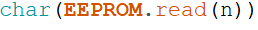
If you notice we are reading it in as a char. On line 22 we convert this char back to a string and append it to a string variable named string_Value with this command.

Notice how we use the String() to convert it. Also we use the += operator to append. It does the same as if you would use this code: string_Value=string_Value+ "some string". As I said in the title "Simple". Now you know the basics how to read your data out of memory.
Section Two: Connecting your IOT device to your WiFi network using the credentials stored in memory
Before you continue with this section first make sure you have entered your WiFi credentials in the ESP8266 huzzah breakout memory using the sketch in section 3 of Part 1 of this tutorial. We are building on top of that data.
Download sketch IOTdevice_read_Config_1_0.ino from this link. At first glance the sketch might look complicated, but that is only because we need to read information out of memory and then convert it to whatever format it needs to be in. If you look past the amount of code everything is straight forward
Near the top of the sketch (starting at line 24) we declare the following variables:
Notice that we declare 2 char arrays; ssid[30] and password[30]. This is needed because the code below (which is needed to connect to your WiFi router) needs this data type to work.

I'll explain this in more in detail in a bit. Next you see the integer ip_group. We use this variable to help parse the IP data out of memory. Each ip address is made up out of 4 groups of numbers, and we need a fifth one to store the last 3 digits of the gateway address. The last variable (string_IP) is used to temporarily store the ip info while we parse the data.
Reading Credentials out of Memory (ssid, Password)
Next we jump to the top of the setup() function. Lest look at the code starting at line 62;
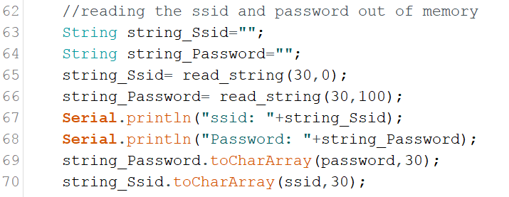
This block of code reads the WiFi routers ssid, and password out of memory. First two Strings() are declare to temporarily store the ssid, and password in. Then the function read_string(int Size,int Location) is called. You pass this function the location (in memory) of the data you want to read out of memory, and the size (in characters) of the data. It returns a String() containing the data you were looking for. Next the Strings gets converted into an Char Array. Remember that a Char Array variable had to use for the ssid and password, well here they are populate them with this command;

String.toCharArray(Char,Size) function converts a String into an Char Array. All you need is the String you want to convert, a Char Array and the size of Array. On line 69, and 70 we convert the temporary strings into the arrays that are going to be used to provide the SSID and Password credentials.
Next lets look at the read_string() function:
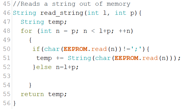
The read_string() function is strait forward. A for() loop that reads one character at a time out of memory. When it encounters the end of data string ';' character it exits the loop and returns the string as an result.
Configuring the IP information
The difficulty with configuring the IP information is that a string containing 4 groups of numbers needs to converted into 4 integers. Lets look at the code and see how it is done;
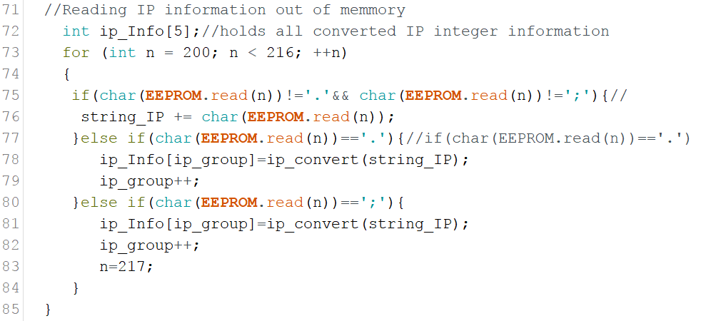
On line 73 a Array is declared of the integer type (ip_Info[5]. It can hold 5 groups of integers (The 4 from the IP, and one group for the gateway. Now remember when using Arrays, the first position always starts at 0. The ip_group variable is used to handle what IP group we are dealing with.
A simple for loop is used to read a string out of memory one character at a time. The if ()/else statement in the loop looks for the '.' and ';' characters (The '.' divides the 4 sets of IP numbers, and the';' is the end of string character) . When one of those characters is found it sends the string_IP string to the ip_convert(String) function. The ip_convert() function converts the string to an integer and returns it. The integer gets store in the ip_Info[] variable using the ip_group variable to determine what slot it gets stored in.
Lets explore the code for the ip_convert() function ;
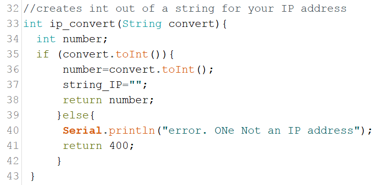
The ip_convert() function starts on line 34 of the sketch. It converts the string send to it to an integer. The syntax to convert a string into an integer is simple String.toInt(). We check if the string actually can be converted to an integer with the in statement on line 35. If it is possible to convert the string, the string_IP variable gets reset to empty and then returns the converted integer containing your IP information. If the string can't be converted to an integer it returns a value of 400 (You can use this for error checking, which I have not implemented).
Next the gateway information is read out of memory with the following code;

It uses the functions described above, saving me time and code size, and making things more streamlined :). Now it is time to put this all together and link the IP information (IP Stack) and credentials (ssid,password) to the ESP8266 and connecting it to your WiFi network. We do this with the following code;
click to enlarge
The IPAddress data type requires 4 integers divided by commas. The IP information stored in the ip_Info[] array gets use to populate the IP variables. Next we bind them to the development board using the WiFi.config() command, and it is time to connect to your WiFi router with the WiFi.begin() code.
The following code checks if the connection is working;
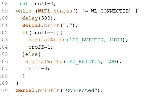
The While() loop uses the WiFi.status() function to check if it is connected. This does not check if the IP information is correct, it only checks that your credentials (ssid,password) are correct. The loop keeps cycling until it connects. I added the blinking onboard LED that blinks until connected.
Configuring the Web Server
I am not going to go deep into the webserver configuration as we have discussed it in detail in Part 1 of this tutorial. All I have done is created /on, and /off functions. The code for this can be found starting on line 113 of the sketch and the actual functions can be found starting on line 127 .
Compile this code and try to type http://insert your ip/on to turn the on board light on, and http://insert your ip/on to turn it off.
Section 3: Creating your user configurable IOT device
Download the completed sketch: complete_IOT_solution_1_0_2.ino here. I have also created a pdf with all functions in this sketch, their short descriptions and the line in the code where to find them. You can download it from here.
This is the final sketch of the tutorial. This sketch is basically WiFiAccessPoint_Write1_0.ino sketch(from Part 1), and the IOTdevice_read_Config_1_0.ino from the previous section mashed together to make one coherent sketch.
As a disclaimer I would like to say that this final sketch is not to be used without you doing thorough testing in a real world environment. I have done testing on it under controlled environment, but it has not had a monkey test done.
To make the two above mentioned sketches work I had to rework some of the variables used to deal with naming conflicts, but all the main functions and parts of the two parent sketches are there and intact.
To make the integration readable and understandable, I moved most of the code located in the setup() function of the parent sketches, and put them in their own functions (WAP(), and IOT()). I only left the shared items, like the setup of the webserver in the setup function.
The biggest change is really that I have altered the hardware configuration by adding a (spst) switch. This is basically a On and Off switch. The connection diagram can be found below. I have created the #define button_Pin 13 variable for the define the switch digital port.

I have set it up so that when the switch is in the On position you go into setup mode, and when it is Off to be in normal mode.
Another big change is part of the error checking. I have added some more comprehensive but still basic error checking with these functions:
- int ssid_error_Check(String content) on line 306
- int password_error_Check(String content) on line 321
- int ip_error_Check(String content) on line 344
- int gw_error_Check(String content) on line 382
These are very simple error check routines. They basically check if the string containing the data is the correct length, and if it contain characters that not allowed in the ssid, password, IP, and gateway. In the case of the IP I check for non alphanumeric characters with isAlpha(). This function returns a true when it contains non numeric characters. I do this with the following code:
It basically creates an error message that gets displayed in the input form if the IP address contains non Alphanumeric characters. A great place to see how to evaluate and analyse strings is this tutorial from the Arduino.cc people; link: https://www.arduino.cc/en/Tutorial/CharacterAnalysis.
The creation of the input web form also has seen some changes. I create a function called create_form(String ssidr,String passwordr,String ipr, String gwr) (on line 218). When you call it you pass it the ssid, password, ip, and the gw address. This is done in the error checking process. If one of the error checking function return a 1 (indicating an error) the input form is returned to the web browser with previously entered values and the appropriate error message. We use the following global error messages variables (declared on line 38).
String ssid_Arg;// Error message for ssid input
String password_Arg;// Error message for password input
String ip_Arg;// Error message for ip input
String gw_Arg;// Error message for gateway input
Compile and upload the sketch and take it for a run. First set the switch into the setup configuration and type in your WiFi credentials. See how the error checking works (remember it is really basic, you might want to add some more checks to it). Then throw the switch into normal operation mode and see how it connects to your WiFi router. Go to the root / of your device with your web browser and how to turn the onboard led on and off.
This completes this tutorial. If you have further questions leave them in the comment section below and I'll try to answer them as quick as possible. I hope you enjoyed this tutorial and it increased your knowledge base so you can become a more accomplished maker.
If you like this tutorial and want to see more of this please subscribe to my periodical Newsletter by filling out the form below, or follow me on Facebook by clicking on this link, and click the Like button on my Facebook page.

Tutorial:Storing WiFi Configuration On Your ESP8266 Using The EEPROM Library Made Simple Part 1
This tutorial is part 1 of 2 that will simplify the way you can store your WiFi configuration on an ESP8266 using the EEPROM library. With this knowledge you can then build Internet Of Things (IOT) projects that can be configured by web form. This will enable to change passwords or IP configuration when needed without having to recompile your sketch.
In part 1 we learn how to write the information to your IOT project, part 2 will teach you how to read this information out of memory and configure your IOT project so it can connect to your WiFi router
| Please put some money in the tip jar by clicking on the donate button to support me so I can continue creating contend like this. P.S. please donate more than $1 as PayPal takes minimum $0.30 per transaction |

In this tutorial we are going to build an IOT device, using the ESP8266, that allows you to setup the network configuration (e.g. SSID, and password of a WiFi router ) through a form and store it in it’s memory. This is a bit harder to do then for instance using an Arduino UNO as the ESP8266 does not really have an EEPROM like all the real Arduino boards have. This is why most of us struggle to use the EEPROM library with the ESP8266 development board.
This is the first tutorial out of a 2 part series. In part 1 I will teach you how to write the data to the ESP8266. In part 2 we will teach you how to read it back out of memory to configure your IOT device to connect to your home network.
Part one has 3 sections. In section One (The EEPROM Conundrum) we will look at how to write data to the ESP8266 memory. Section Two (Setting up a basic WAP) will explain how to set up an WiFi Access Point.
"An access point is a device that creates a wireless local area network. or WLAN, usually in an office or large building. An access point sometimes connects to a wired router, switch, or hub via an Ethernet cable, and projects a Wi-Fi signal to a designated area. It is also used for users to configure IOT devices for first time use, or password changes"
In Section Three ( Adding a form to the WAP, and write data to huzzah memory ) we will put it all together to create a functional WiFi access point that writes configuration data to your ESP8266 memory
Below is a You Tube video accompanying this tutorial. For best result download the example sketches within this tutorial before watching this video.
Materials Needed in this tutorial
- The Adafruit ESP8266 Huzzah Breakout board
- 5v ftdi cable
- Access to the the SSID and password of your WiFi router you want to connect to, to get configuration data
Section One:The EEPROM Conundrum
Because many makers want to build cheap IOT solution, the ESP8266 has become a favourite to a lot of us. But writing values other than integers to its memory can be problematic. The main reason is that the standard EEPROM library does not work, because the ESP8266 does not have an EEPROM. The library we use simply emulates an EEPROM but in real life we are writing to the FLASH Memory.
Writing to the ESP8266 memory
The trick is simple; anything we write to the ESP8266 memory will have to be a string, and we can write them one character as a time. Download the sample sketch from this link:
#include <EEPROM.h> //The EEPROM libray
String string_Value;
float float_Value=111.2222;


void setup() {
string_Value=String(float_Value,4);
string_Value=string_Value+";";
EEPROM.begin(512);
for(int n=0; n< string_Value.length();n++){
  EEPROM.write(n,string_Value[n]);
}
EEPROM.commit();
}

void loop() {
  // put your main code here, to run repeatedly:

}
As you can see the code is very simple. Let me explain what we do. First we declare a String variable called string_Value and a float variable float_Value with a value of 111.2222
String string_Value;
float float_Value=111.2222;
Next in the setup() function I convert the float variable into a string. I do this using the String object. If you notice the "4" in the String(float_Value,4), this signifies the precision of the float value that gets stored in the string_Value variable. If you notice I added the "; "character to the string value.
string_Value=String(float_Value,4);
string_Value=string_Value+";";
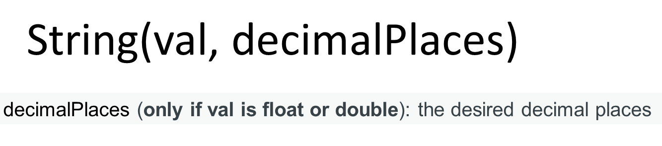
I add the ; character as an end of string symbol. When you read data one character at a time you need to know when you have reached the end of the data. The easiest way to do this is by adding a predetermined character that symbolizes the end of data stream. I chose the ; character as you are not allowed to use them in most passwords, or URL's.
Now comes the writing process, I first initiate the EEPROM function with EEPROM.begin(512);, and I also set the size of the storage as well. Next I cycle through the string value string_Value one character at a time using a for() loop. I start writing these characters to the ESP8622 memory starting at position 0 with this command EEPROM.write(n,string_Value[n]).


"If you look at the memory we defined as a chest of drawers with 512 drawer. The first drawer has an address of 0, and the last drawer has a address of 511. As the sketch walk's through the string one character at a time, it opens the drawer with the corresponding address and deposits the character in that drawer. "
The write position in the ESP8622's memory get determined by the value n which I set to 0 in the initialization section of the for loop. I use the string.Value.length() to set how many times we go through the for loop. After the loop terminates I commit the data written to memory with EEPROM.commit()
As you see it is quite easy. You can write any value you want to the ESP8266 memory this way as long as you first convert it to a String.
Section TWO: setting up a basic WAP
Access Points are fun little things that allow you to connect to your Arduino projects to do interesting things like, get or store data that is password protected, create your own WiFi router, or for our purpose to let the user configure your project.
In this section we are setting up a basic WAP. It will allow you to give your WAP a name like a WiFi router( the SSID), require a password for authentication and security purposes, and provide you with a static IP address so you can access the web server to get information.
At the top of the sketch you see the following section near line 20 in your sketch
/* Configuration Variables for the AP name and IP. */
const char *ssid = "Test";
const char *password = "Password";
IPAddress ap_local_IP(192,168,1,1);
IPAddress ap_gateway(192,168,1,254);
IPAddress ap_subnet(255,255,255,0);
These variables set up the WAP environment. The ssid variable gives your WAP its name, and the password provides you with a password. You can change this to whatever your heart desires. Here you can also find 3 variables that define the IP information. If you understand a little bit about the IP configuration you can alter this to your liking. The IP, Gateway, and subnet get bound to the board with the following commands you can find in the setup() function roughly at line 33 in the sketch and write below it we set the name and password for the AP ;
WiFi.softAPConfig(ap_local_IP, ap_gateway, ap_subnet)
WiFi.softAP(ssid, password);
You are now ready to connect to the WAP. It still would not do anything as we have to add a service to provide. We are going to add a web-server. We do this with the following line found in your sketch on line 19;
This line adds a webserver listening on port 80. Now it is time to add some content to the webserver. We do this by adding the following lines to the setup() function near line 41.
server.on("/", handleRoot);
server.onNotFound(handleNotFound);
server.begin();
The first line tells the server to execute function handleRoot() when somebody accesses the root of the server. In our case if somebody would type http://192.168.1.1/. The next line will execute function handleNotFound() if somebody would try to access anything else other then the root of the server.
If you look at the bottom end of the sketch you actually see both functions handleRoot() and handleNotFound(). The handleRoot() function has this line of code in it;
server.send(200, "text/html", "<h1>You are connected</h1>");
This line basically sends a response to the request for data when you type http://192.168.1.1/ into your web browser and press enter. The send() function basically is made up like this; send(code,content type,content).
The code parameter is basically the type of response the webserver gives. The two most common are 200 (which means this is success full response and here is what you requested), or the 404 (which means the data requested does not exist). The next parameter is content type. For us it is plain html (text/html), and the next parameter is the actual content. In our case it is;
"<h1>You are connected</h1>"
This can also be a string variable that contains html code. If you look at the handleNotFound() function you see that we first create a string called message where we store the html response of the server not finding the requested page. Then in the send() function we give a code of 404 (page not found), a content type of text/plain, and the content is the message string.
The final component in setting up the webserver is the line server.handleClient(); in the loop() function of the sketch. The server.handleClient(); listens to the IP address provided and will call the appropriate function declared in the setup() function. Now your webserver is ready. Compile your sketch and upload it to your huzzah breakout and see what happens.
Section Three: Adding a form to the WAP, and write data to huzzah memory
In this section we combine Section one and two of this tutorial to get a WAP that writes information you enter into a form to memory. I am not going to rehash all the points explained in the previous sections, I am just going over the new stuff. Start with downloading the sketch "WiFiAccesspoint_Write1_0.ino" by clicking on this link.
The first major difference is that we create a constant char near line 17 of the sketch named INDEX_HTML. This contains the form html data that we are going to display.
The next big change you can find is near the bottom of the sketch in the handleRoot() function(on line 79 of your sketch). It has a if() statement that checks if the data received by the web server contains the input field information of the form created on line 17 of the sketch. This is done by checking for the names assigned to the input fields on the html form. See the example of an html input field below.
<input maxlength="30" name="ssid">
The following code checks if the input field name "ssid" is one of the parameters received by the webserver when you submitted it. If it did it returns a value of true, if not it returns a value of false;

The if() statement below makes sure that all field name parameters are present.

If this is true we call the handleSubmit() function. If this is not true we display the html input form.
In this sketch we don't check if the data entered is correct. If this would be a completed sketch to be used in the field it would be imperative to check this.
If the input field names exists and the if statement returns as true, we call the handleSubmit() function (on line 87 of your sketch). In this function we create an html page displaying the data the user just entered, and we call the write_to_Memory() function (on line 108 of your sketch).
We pass this function the content of each input field found in the html form. You get the content of the form input field named "ssid" with the code below;
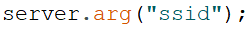
This code returns the value of the form input field as a String.
In the write_to_Memory() function the end of data symbol ";" is added to each fields data and call the write_EEPROM( ) function to write it to memory. At the end of the write_to_Memory() function we commit the data to memory using the EEPROM.commit() code.
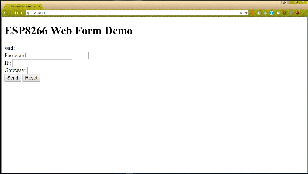
Compile your sketch and upload it to your ESP8266. Now use a laptop or other device to connect to your WAP. If you did not change the ssid name look for the name Test in your available WiFi connection point. Use Password as the password. After it completes connecting to your IOT device start up a web browser and type 192.168.1.1 in your URL bar and press enter. A form pops up, and you are ready to type in your WiFi router credentials and press enter. Your information is now written to your ESP8266.
This completes this tutorial , check back in a week or two for Part 2 of this tutorial where we will learn how to read the data back and how to put these two sections together. If you have further questions leave them in the comments below.
If you like this tutorial and want to see more of this please subscribe to my periodical Newsletter by filling out the form below, or follow me on Facebook by clicking on this link, and click the Like button on my Facebook page.

Halloween Hack: How to automatically activate your Halloween Arduino Project
Halloween Hack: How to automatically activate your Halloween Arduino Project
With Halloween coming around the corner it is time to see how we can automate some scary projects. We are going to explore two of my favourite ways to do this. First we are going to look how to integrate a pressure plate switch (a big push button you step on which we are going to build), then we will look at how to connect a motion sensor (Passive Infrared Sensor or PIR) to your scaretastick project for the maximum scare factor. I recommend you also watch the video below to get the most out of this tutorial.
| Please put some money in the tip jar by clicking on the donate button to support me so I can continue creating contend like this. P.S. please donate more than $1 as PayPal takes minimum $0.30 per transaction |
With Halloween coming around the corner it is time to see how we can automate some scary projects. We are going to explore two of my favourite ways to do this. First we are going to look how to integrate a pressure plate switch (a big push button you step on which we are going to build), then we will look at how to connect a motion sensor (Passive Infrared Sensor or PIR) to your scaretastick project for the maximum scare factor. I recommend you also watch the video below to get the most out of this tutorial.
Integrating your Pressure Plate switch
One of the most used activators of any Halloween projects is a pressure plate switch, which you can hide under a mat. Your unsuspecting victim steps on your door mat activating your amazing Halloween project, and scares the socks off them.
But how do we connect this to your Arduino and write the code for it. First let’s look how we can build a simple pressure plate switch:
Materials and tools needed for your pressure switch:
Materials:
- 3 identical pieces of corrugated cardboard about half a centimeter thick
- Aluminum foil
- Masking tape
- Glue or double sided tape
- Hookup wire long enough for your purpose
Tools:
- Utility Knife
- Ruler
- Wire stripper
Building Steps
Before you begin make sure the width of your cardboard is the same or smaller than your aluminum foil you are going to use.
Step 1:
With your utility knife cut the center out of one of your pieces of cardboard leaving a border of about 3 cm to 4 cm.
Step 2:
Use glue or double sided tape to affix your aluminum foil to the 2 remaining pieces of cardboard. Make sure that your aluminum foil is well adhered to the cardboard so it doesn't sag.
Leave a small border (4cm / 1 inch) without aluminum foil around the edges (In my picture it is not visible because I forgot to do it). If you don’t do this you have the chance that you create a short, resulting in your project not functioning correctly (which happened to me ).
Step 3:
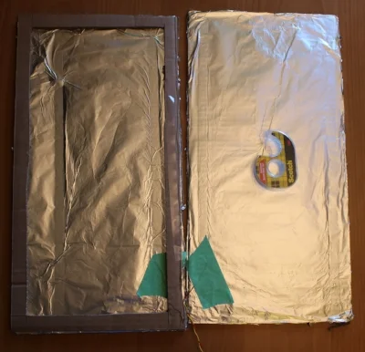
Strip one end of your hookup wires exposing 5 cm/2 inches of the copper wire inside. Lay the 2 pieces of cardboard next to each other with the aluminum foil facing up. Use masking tape to tape the exposed copper wire to the aluminum foil.
Step 4:
Affix the 3rd piece of cardboard (The one with the center cut out) to one of the aluminum foil covered sides. Now place the other Aluminum foil covered piece of cardboard on top (aluminum foil facing down) creating a sandwich. If you have a multi meter test the switch(before taping this all together) to make sure you don't have a shorts.
Tape the 3 layers of cardboard together so they are fixed in place and can’t slide or move, and your switch is completed
Connecting the Pressure Plate Switch to your Arduino
Now you have created a pressure plate switch (or a very large push button) it is time to connect it to your Arduino. A pressure plate switch is a really big temporary switch or push button. To connect one of these things to your Arduino you going to need:
- An Arduino or compatible
- 10 K resistor
- Breadboard
- Jumper wire
- Your completed pressure plate
Connecting your pressure plate is much like connecting any temporary switch/button to your Arduino. The following diagram shows what it would look like if you connect it to an Arduino Uno.
As you see connecting it to your Arduino is a breeze. Take your 10K resistor and connect it to 5v as seen on the diagram. Connect one lead of your Pressure Plate to ground and the other one to your 10K resistor as displayed in the diagram. Next connect a jumper wire from the 10K resistor to digital pin 2 on your Arduino.
The most complex part of this setup is that 10K resistor. This is what we call a pull up resistor. Its purpose is to eliminate false readings from you digital input pin on your Arduino. I am not going to go deeper into the workings of this pull up resistor as it falls out of the scope of this tutorial.
The Code for your Pressure Plate
Here is where the rubber meets the road. Although connecting your components correctly is paramount for a successful project, writing the code actually make things happen. One of the most basic things we handle is a push button. But lots of people are still do this wrong.
If you don’t create a debounce system in your code you get many erroneous inputs from this button. Without debouncing a button, one press of the button (or one step on the pressure plate) might be interpreted by the microcontroller as many button presses. This is because of the mechanical properties of these push buttons and the speed the microcontroller reads the inputs.
The way we are going to debounce the button is by counting milliseconds. We set how many milliseconds we want to wait until we allow the next action from a button. To do this we use the millis() function.
The millis() function basically returns in milliseconds how long your sketch has been running. After about 50 days the millis() number has become so big that it returns to 0 and the fun start all over again.
How does this work?
We create two variables:
unsigned long debounceDelay = 1000;
The debounceDelay variable tells the sketch how long you want to wait before the next action (in milliseconds). The lastDebounceTime variable gets a new value every time the button gets pressed, and the wait time set by the debounceDelay variable has expired. It uses the millis() function to get its new value.
lastDebounceTime=millis();
action();
}
I have created two example sketches. One that will activate your project when somebody steps on the plate (step_on.ino) and one that will activate your project when stepping off the plate (step_off.ino). You can download them by clicking on the links below
In the sketch you only need to edit the debounceDelay value to your preferred delay time (in milliseconds). You copy your code in the action() function found at the bottom of the sketches provided. Don't forget to also copy your includes and variables you have created to the top of the sketch, and modify the setup() function to reflect your needs.
//your code goes here
}
Using a motion sensor (Passive Infrared (PIR) Sensor)
A motion sensor operates much like a button. If somebody is in the line of sight of the infrared beam it sends a signal to the digital pin on your Arduino (pulls the pin high). Lets take a closer look at how to integrate your PIR sensor into your project.
Materials needed:
- An Arduino or compatible
- Jumper wire
- A PIRmotion sensor
As you see in the diagram it is a very simple process to connect your motion sensor. You connect the power in lead to 5V and the ground lead to gnd on the Arduino Uno. The signal lead goes to digital pin 2 on your Arduino, and your sensor is ready for some code.
How does the code works
The sketch for the motion sensor works much the same as the sketches for the pressure plate switch. We use the same variables and also include the action() function to copy your code in. You can download the sketch named pir_sensor.ino here.
In this example we use the debounceDelay variable to delay the activation of your project not because of electrical noise, but to stop the project from constantly working because people stand in the beam
Now you just need to copy your code in the appropriate places (the action() function) and alter the debounceDelay variable to your liking. If you bought a PIR sensor with adjustments you can tune down the sensitivity of your sensor. The sensor I am using doesn't have that capability. To reduce the sensitivity of my sensor I created a protection hood that only allows a small amount of the infrared beam to return to the sensor.


If you like this tutorial and want to see more of this please If you are interested subscribe to my periodical Newsletter by filling out the form below, or follow me on Facebook by clicking on this link, and click the follow button.

Helpful Tip: How to create a more professional and user friendly Arduino project by storing your configuration in the EEPROM
As makers we strive to make projects that are easy to use and have a more professional feel about them. If your project is user configurable (e.g. are you using C or F for your temperature), how do you store that information so it is kept, even when the Arduino gets reset?
What if you could make your Arduino remember these types of user changeable settings (e.g. using a menu saving your Wi-Fi password)?
| Please put some money in the tip jar by clicking on the donate button to support me so I can continue creating contend like this. P.S. please donate more than $1 as PayPal takes minimum $0.30 per transaction |

As makers we strive to make projects that are easy to use and have a more professional feel about them. If your project is user configurable (e.g. are you using C or F for your temperature), how do you store that information so it is kept, even when the Arduino gets reset?
What if you could make your Arduino remember these types of user changeable settings (e.g. using a menu saving your Wi-Fi password)? The solution is using the EEPROM library. This library allows you to store your configuration data like your WIFI router name and password, and be able to change it if you get a new router or password. The drawback is that you can only write and erase data 100,000 times so be careful to only write the most important data. Luckily you can read this data as many times as you want without any issue.
To write your data you use the; EEPROM.write(address, value), and to read your data you use the EEPROM.read(address). The drawback is that writing anything other than an integer can be complicated.
In the next weeks, I will be writing a tutorial on how to write your configuration or other information to your Arduino/Compatible so you too can create professional looking projects.If you are interested subscribe to my periodical Newsletter by filling out the form below, or follow me on Facebook by clicking on this link, and click the follow button.

Cooling down your Aquarium by using a temperature controlled Fan
Every aquarium lover is afraid of hot weather. It often means that your tanks are going to be overheating. This can lead to catastrophic results. An easy fix for smaller tanks is to place a small USB fan on top of your tank. It can drop the temperature of your tank by almost 3C less than the the ambient room temperature.
The drawback is that you have a lot of water that evaporates, and your tank temperature can get too cold if your ambient temperature in your room drops. This is why I created an electronic switch using an Arduino that turns the USB fan on or off depending on the temperature of the water.
| Please put some money in the tip jar by clicking on the donate button to support me so I can continue creating contend like this. P.S. please donate more than $1 as PayPal takes minimum $0.30 per transaction |
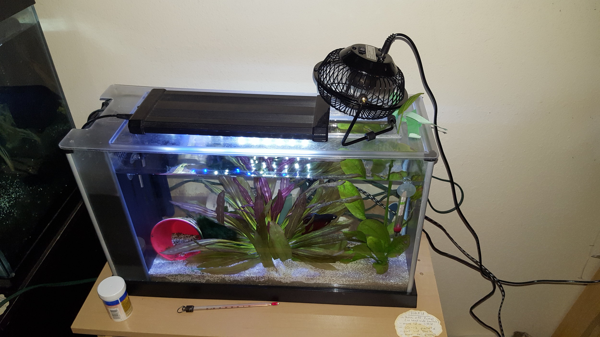
Every aquarium lover is afraid of hot weather. It often means that your tanks are going to be overheating. This can lead to catastrophic results. An easy fix for smaller tanks is to place a small USB fan on top of your tank. It can drop the temperature of your tank by almost 3C less than the the ambient room temperature.
The drawback is that you have a lot of water that evaporates, and your tank temperature can get too cold if your ambient temperature in your room drops. This is why I created an electronic switch using an Arduino that turns the USB fan on or off depending on the temperature of the water.
I created a list of what you need and where to get it. I also created a diagram how to put it together, and even wrote the sketch that operates this all.
What you need:
|
QTY |
Description |
Cost |
Total |
Supplier |
SKU |
|
1 |
ENCLOSURE,
PLASTIC BOX LX 422 101X40X52MM |
2.99 |
2.99 |
Lee's
Electronics |
10361 |
|
1 |
Printed
Circuit Board |
1.7 |
1.7 |
Lee's
Electronics |
10496 |
|
1 |
Arduino
Pro Mini |
23 |
23 |
Lee's
Electronics |
11008 |
|
1 |
USB
Charing Cable 1 M |
6 |
6 |
Amazon |
|
|
1 |
DS18b20
waterproof Temperature Sensor |
13.25 |
13.25 |
Lee's
Electronics |
1255 |
|
1 |
STANDOFF
PLASTIC F/M M3X12MM 10PCS |
2.8 |
2.8 |
Lee's
Electronics |
62650 |
|
1 |
SCREW
NYLON PLASTIC M3 6MM 10PCS |
2.5 |
2.5 |
Lee's
Electronics |
61569 |
|
1 |
transistor
2n2222 5pcs |
1 |
1 |
Lee's
Electronics |
7174 |
|
1 |
Misselanious
wire/others/Resistors 1K/4.7K |
5 |
5 |
Lee's
Electronics |
|
|
1 |
ChillOut®
6" Manual Control USB & AC Adapter Desk Fan, Black |
19.99 |
19.99 |
Staples |
580700 |
Lee’s Electronics web site is: http://leeselectronic.com
How To Connect the components
Connecting the DS18B20 water Proof Temperature Sensor
|
Sensor |
To: |
Notes |
|
Red
Wire (Vin) |
5V |
Can be
different colour |
|
Black
Wire (GND) |
GND |
Can be
a different colour |
|
Data
Wire (White) |
D2 on
Arduino/Pullup 4.7K resistor to 5V |
Can Be
a different colour |
Connecting the Fan to NPN 2N2222 resistor.
|
USB Fan |
TO |
Notes |
|
Connect
red Wire |
5V |
|
|
Black
Wire |
Collector
NPN transistor |
|
Connecting NPN 2N2222 resistor Flat side facing you.
|
NPN
Resistor |
TO |
Notes |
|
Collector
Pin 3 |
GND
Fan (Black Wire) |
|
|
Base
Pin 2 |
1K
Resistor Connected to Pin 10 |
|
|
Emitter
Pin 1 |
GND |
|
Quick build overview
Start with cutting of the USB part of your Fan purchased at Staples. As Stated connect the red wire to 5V and the black to the collector pin of your transistor. If you use a different Fan make sure you know what colour wires you need to connect, otherwise you have a good chance it will run backwards or not at all.
If you have an unused USB charger cable laying around you can cut the mini plug off the end. Check with a multi meter what wire is power and which is ground. Connect power to the raw pin of your Arduino Pro Mini and the gnd to the gnd of the Pro mini.
Before you solder Steps
Completed PCB in the enclosure
Use the PCB as a guide to drill holes in your enclosure for the standoffs. Screw the standoffs in the holes and use a knife to trim of the excess from the back. Drill a whole big enough to put all the cables through in the side of the enclosure.
Build Diagram
Pull the wires through the whole you just drilled before you start soldering. Follow the Build diagram how to connect everything and solder it on the PCB.
Arduino Sketch
The Arduino Sketch you can download from here. In the top of the sketch there is a variable called maxtemp. This indicates the maximum temperature you want your aquarium to get before the fan is turned on. You also going to need the following libraries:

Tutorial: Using Interrupts to improve the functionality of your Arduino projects
A couple of weeks back I wrote a short tutorial on using timers instead of delay() functions to make your Arduino projects more responsive to input from buttons and sensors. Using interrupts is a different way to achieve the same result. By attaching an interrupt to a digital pin the Arduino will halt what it is doing to handle the input as it happens making your project more responsive.
EXPLAINING WHAT AN INTERRUPT IS AND DOES.
Let’s say you are listening to your music with your noise canceling headphones on. At that point somebody calls you on your cell phone. Of course you don’t hear your phone ring as your music is loud and you are distracted by it. Luckily there is someone in the room with you who hears the ringing. This person pokes you in the side to let you know that your phone is ringing and tells you can answer it.
| Please put some money in the tip jar by clicking on the donate button to support me so I can continue creating contend like this. P.S. please donate more than $1 as PayPal takes minimum $0.30 per transaction |
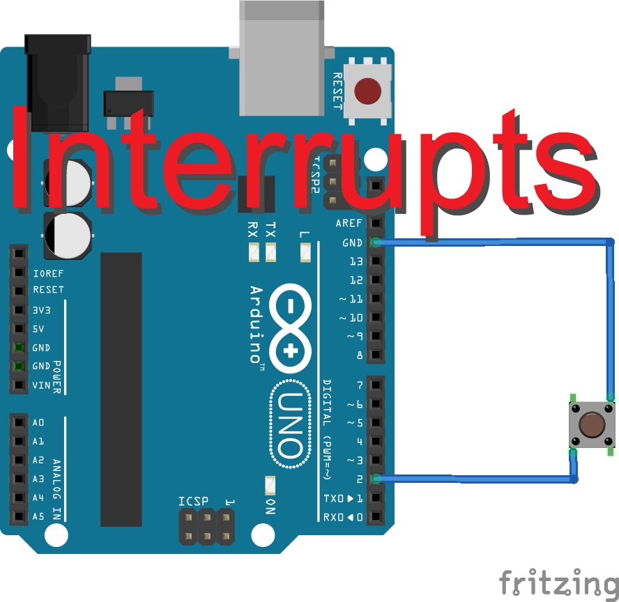
A couple of weeks back I wrote a short tutorial on using timers instead of delay() functions to make your Arduino projects more responsive to input from buttons and sensors. Using interrupts is a different way to achieve the same result. By attaching an interrupt to a digital pin the Arduino will halt what it is doing to handle the input as it happens making your project more responsive.
Explaining what an interrupt is and does.
Let’s say you are listening to your music with your noise canceling headphones on. At that point somebody calls you on your cell phone. Of course you don’t hear your phone ring as your music is loud and you are distracted by it. Luckily there is someone in the room with you who hears the ringing. This person pokes you in the side to let you know that your phone is ringing and tells you can answer it.
An interrupt works much the same. Your Arduino is distracted by running the code you wrote. It might not notice inputs from buttons or sensors. The interrupt is the person in the room that tells the Arduino to respond to the button press.
Most Arduinos have Interrupts attached to hardware pins. The table below has a list of Arduino’s and what pins have interrupts attached to them. If your board is not on this list just check the specs of your board to see what pins have an interrupt attached to them.
|
Board |
int.0 |
int.1 |
int.2 |
int.3 |
int.4 |
int.5 |
|
Uno,
Ethernet |
2 |
3 |
|
|
|
|
|
Mega2560 |
2 |
3 |
21 |
20 |
19 |
18 |
|
32u4
based (e.g Leonardo, Micro) |
3 |
2 |
0 |
1 |
7 |
|
You can attach an input sensors or buttons to one of those pins. When the sensor/button provide input to one of the interrupt pins your Arduino will halt what it is doing and run the code you attached to that pin.
The Code
In your setup() function you would have a line to attach the interrupt to the pin.
attachInterrupt(digitalPinToInterrupt(pin), ISR, mode);
- pin: is the number of your hardware pin you want to use
- ISR: is the function that contains the code that you want to run
- Mode: defines when the interrupt should be
triggered. Four constants are predefined as valid values:
- LOW to trigger the interrupt whenever the pin is low,
- CHANGE to trigger the interrupt whenever the pin changes value
- RISING to trigger when the pin goes from low to high,
- FALLING for when the pin goes from high to low.
Here is a simple snippet of code that you will find when looking for this topic online. It connects a pushbutton to pin 2 of an Arduino Uno. When you press the button the led on pin 13 will either turn on or of
const byte interruptPin = 2;
volatile byte state = LOW;
void setup() {
pinMode(ledPin, OUTPUT);
pinMode(interruptPin, INPUT_PULLUP);
attachInterrupt(digitalPinToInterrupt(interruptPin), blink1, CHANGE);
}
void loop() {
digitalWrite(ledPin, state);
}
void blink1() {
state = !state;
}
Notice the variable state has the volatile property added to it. This stores the variable in a memory space so that when changed by the interrupt function it gets changed throughout the whole sketch. It will become clear why that is required later on.
Example
To illustrate the effect of the Interrupts we are going to create a project that has 4 LED's that will blink in sequence with a one second interval between them. You will have a push button that will light all the lights at once when pressed. Below is a list of materials you need. You also have to download the two example files.
interrupt_demo1.ino uses a normal digitalRead() to look for the input from the button. In this example it can take up-to 4 seconds before the button will execute. In the interrupt_demo2.ino we use the attachInterrupt() function to read the button input. In this case the button responds instantly.
Downloads:
Part List
| Amount | Part Type | Properties |
|---|---|---|
| 2 | Red LED | color Red ; package 5 mm [THT]; leg yes |
| 2 | Yellow LED | color Yellow ; package 5 mm [THT]; leg yes |
| 1 | Arduino Uno (Rev3) - ICSP | type Arduino UNO (Rev3) - ICSP |
| 4 | 330Ω Resistor | resistance 330Ω; tolerance ±5%; bands 4; package THT |
| 1 | Pushbutton | package [THT] |
In the first example we use the button without the interrupt attached on on pin 2 and use the conventional way to look at inputs. When pressing the button you will experience delays in execution and it will seem the button is not functional. You will notice that I don't use a pull up resistor on the button. We use the internal pull up resister on pin 2 with by using this code:
In example 2 we use the interrupt connected to pin 2. The respoce of the button press is almost instantaneously. When the interrupt is triggered by pressing the button the Arduino will execute the code in the function blink1(). The moment that code has been executed it will return to where it previously left off. This is why I have the if statement (as you see below) behind every delay to bring us back to the beginning of the loop.
Without the if statement the state variable would have changed it's value, but the program would not use this until it ran through all the code and would reach the top of the loop.
In conclusion
The attachInterrupt() function works great for buttons, but in practice it gets used more for input from sensors like IR receivers, or motion sensors. Be aware to use the volatile property for global variables that get changed by the interrupt.
Also remember that the program will resume where it left off when the code in the interrupt function has finished. If you want to change that you need to add conditional statements that alter the path of your code.

Project: IOT Weather Forecasting Station
Project: IOT Weather Forecasting Station
The most discussed topic in the western world is the weather. We speak about it around the water cooler, at the bus stop, and in elevators. If you only could have a magical cube that could tell you the weather on your desk or near the water cooler.
Now you can. I created an IOT weather cube that you can build yourself. The IOT weather cube will display the current conditions and with the click of a button you can see up to 3 days of weather forcast for your region.
All you need is a few parts, some soldering skills, a free development account on wunderground.com, and a Wi-Fi router connected to the internet. I’ll supply the pictures how to connect the wires, the code, and even the drawings for getting your own box cut on a laser cutter.
| Please put some money in the tip jar by clicking on the donate button to support me so I can continue creating contend like this. P.S. please donate more than $1 as PayPal takes minimum $0.30 per transaction |

The most discussed topic in the western world is the weather. We speak about it around the water cooler, at the bus stop, and in elevators. If you only could have a magical cube that could tell you the weather on your desk or near the water cooler.
Now you can. I created an IOT weather cube that you can build yourself. The IOT weather cube will display the current conditions and with the click of a button you can see up to 3 days of weather forcast for your region.
All you need is a few parts, some soldering skills, a free development account on wunderground.com, and a Wi-Fi router connected to the internet. I’ll supply the pictures how to connect the wires, the code, and even the drawings for getting your own box cut on a laser cutter.
Tools
All you need for tools are a soldering iron, wire strippers and cutters. A small vise or helping hands with banana clips to hold your small items steady when soldering.
Most people don’t have laser cutter in their garage (including me) to cut your box. But most cities have service centers or hacker spaces where you can get this done for a minimal fee.
You also going to need a hot glue gun and some double sided foam tape to attach your Huzzah breakout board to your project box.
Downloads
Shopping List
| Amount | Part Type | Properties |
|---|---|---|
| 1 | Adafruit HUZZAH ESP8266 Breakout | variant A; part # 2471 |
| 1 | Nokia 5110 LCD | |
| 1 | 10Ω Resistor | tolerance ±5%; resistance 10Ω; package 0603 [SMD] |
| 1 | Pushbutton | panel mount SPST;; diamiter 6mm |
| 1 | Toggle Switch | switching circuit SPDT; package THT |
| 1 | Round Pushbutton | panel mount SPST; default state Normally Open diameter 7mm |
| 1 | USB Connectors | SparkFun microB USB Breakout 12035 |
| Wire Assortment | Hookup wire | |
| 6 | Male header pins | 15mm/5mm pin lenght for huzzah programming |
| FTDI Cable | 5V |
Step 1 WUNDERGROUND.COM development account/API

wunderground.com is one of the many weather streaming sites that provide up to date weather information. You can access this information by requesting it using an API key using a specific web request format. They will send you the weather data back in a pre-specified format so our Arduino sketch is able to read this data..
This type or request and response require an Application Programming Interface (or API for short) that the service provider (wunderground.com in this case) creates so people like us can get data from them.
Signing up for an account
To do this you first need an account with them by clicking on this link and going through the process for signing up for an account. When you have received their conformation email and you have verified your email with them it is time to create an API key.
You create and API key by clicking on this link and creating a development account and requesting the API key. On this page select the Anvil plan, select the free developer account and click the Purchase key button. On the next page you have to supply your name, email, give a project name, and provide a web site. Look at the image below how to answer the rest of the questions. Finally you are getting the api key. This 16 digits key is important information you need to keep. Note it down
Step 2 Collecting your WI-FI credentials and you GPS location.
You are going to need your SSID and password to connect to your WI-FI router. Use google maps to get your GPS locations. This locations has 2 numbers that look something like this 49.263173, -123.110683. For our purpose you need to trim this back to look like this 49.263, -123.110. You are going to need this information later when it is time to modify the Arduino sketch to customize it for your purpose.
Step 3 Connecting all your parts together
It is a good idea to get your project box first. This way you know how long your hookup wires need to be. Make sure you have the hookup wires that you solder to the Huzzah breakout board come from the top and the wires that come from the Nokia display come out of the back. If you are planning to use my laser cut box plans first read that section at the bottom of the page
If you are using my laser cut box as a project case, only solder the header pins for programming on to the Huzzah breakout board. Use longer ones so you can bend them 90 degrees. Just follow the table to see what pin goes to what connection. Just click on the image for a better look.
Connection Table
A quick note about the switch connected to pin 0 on the huzzah. If you pull the pin to ground by placing the switch in the appropriate position the red led will turn on. If you would do a power cycle the huzzah will boot so you can upload a sketch too it. After the power cycle move the switch back into it’s neutral position. This way you can make a small hole in your project box (and let the switch and the programming header be exposed) and be able to reprogram your huzzah if you change passwords or WI-FI networks.
Step 4 Uploading the code
To upload the code to the huzzah you need to first download all required libraries and sketch files. The Nokia 5110 library is a modified Adafruit version for use with the Adafruit Huzzah breakout board. I got it on Githup from user bbx10. If you already have the normal Adafruit library installed you have to replace it for this project. To learn how to install libraries click on this link
If you have never worked with the Adafruit Huzzah breakout board and how to install the drivers required in your Arduino IDE follow this link to the Adafruit tutorial. They always do a great job.
When extracting the huzzah_wunderground_weather_station_v4.zip file make sure that both the .ino and the icon.h file are in the same folder. Before uploading the sketch open up the huzzah_wunderground_weather_station_v4.ino file.
At the top of the file just under the header information you can find 4 variables (ssid, password, gps,api) you still have to enter your information. Replace the text between the quotation marks with your information, e.g. behind the ssid enter your ssid between the quotation marks. After making these changes and saving the file you can upload it to your huzzah breakout. If you have soldered the switch to pin 0 make sure that it is in the neutral position.
Step 5 The laser cut cube
The wood is 6 mm plywood. Below you can download the files you can bring for laser cutting. All measurements are in millimeters. I have created 2 files for the laser cutter. The 90cm v2 box with notations.svg (you can download by clicking on link) has instructions in it for the laser cutting process. Don't use it for the actual laser cutting. Use 90cm v2 box.svg for this purpose (you can download by clicking on link) You can use Inkscape to edit them. It is a freeware you can find on the net for free.
Check out the photo slide show below and read the comments to get a better understanding how every thing fits together.
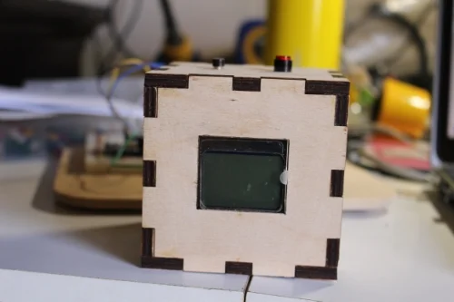

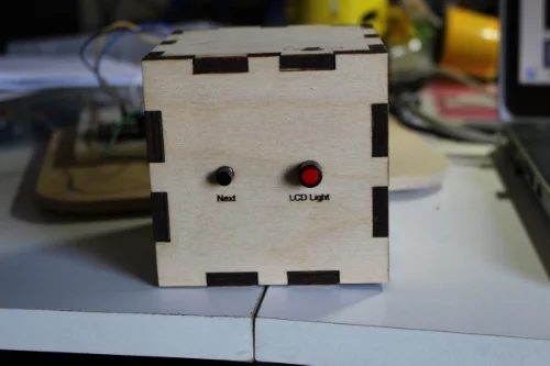
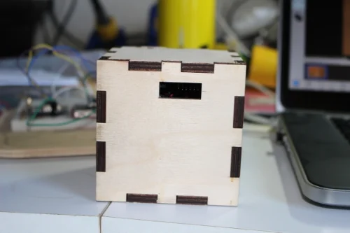
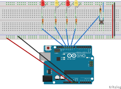
Tutorial: How and Why to use Timers instead of the Delay() Function
Tutorial: How and Why to use Timers instead of the Delay() Function
A common problems with Arduino projects is that buttons or other input input sensors seem to be working intermittently or with a postponed reaction. In cases like this your project might be suffering from delays.
From the beginning we get taught to use the delay() function if we want to create timed delays on execution of specific parts of our Arduino sketch. The drawback is that your loop gets halted and functions above and below the delay() are not being executed during this interval.
A timer approach is a little harder to implement but will allow your main loop to keep executing and only exclude the code and functions you want to exclude. To simplify this we can use timer libraries like the elapsedMillis.
| Please put some money in the tip jar by clicking on the donate button to support me so I can continue creating contend like this. P.S. please donate more than $1 as PayPal takes minimum $0.30 per transaction |
A common problems with Arduino projects is that buttons or other input sensors seem to be working intermittently or with a postponed reaction. In cases like this your project might be suffering from delays.
From the beginning we get taught to use the delay() function if we want to create timed delays on execution of specific parts of our Arduino sketch. The drawback is that your loop gets halted and functions above and below the delay() are not being executed during this interval.
A timer approach is a little harder to implement but your main loop keeps executing and only exclude the code and functions you want to exclude. To simplify this we can use timer libraries like the elapsedMillis.
Click here to download the elapsedMillis library
Let’s take a quick look at some simple examples below.
The first step is to include your library and create a instance variable of the library You can do that in the top of your sketch. See below how that is done:
#include <elapsedMillis.h> //load the library
elapsedMillis timeElapsed;//Create an Instance
Now in your loop you use an if() statement to check if the appropriate interval has elapsed: and reset your timer back to zero. If you want to execute a block of code every 5 seconds you would do something like this:
loop(){
if (timeElapsed > 5000)
{
Do Something
timeElapsed = 0; // reset the counter to 0 so the counting starts over...
}
}
Example
To illustrate the effect of delays we are going to create a project that has 4 LED's that will blink in sequence with a one second interval. You will have a push button that will light all the lights at once when pressed.
I created 2 example sketches to show the effects of the delay() function and what happens when using the elapsedMillis.h library. To recreate the demo you are going to need the hardware listed below
Part List
| Amount | Part Type | Properties |
|---|---|---|
| 2 | Red LED | color Red ; package 5 mm [THT]; leg yes |
| 2 | Yellow LED | color Yellow ; package 5 mm [THT]; leg yes |
| 1 | Arduino Uno (Rev3) - ICSP | type Arduino UNO (Rev3) - ICSP |
| 4 | 330Ω Resistor | resistance 330Ω; tolerance ±5%; bands 4; package THT |
| 1 | 10kΩ Resistor | resistance 10kΩ; tolerance ±5%; bands 4; package THT |
| 1 | Pushbutton | package [THT] |
Hardware Setup
Recreate the hardware setup shown below. You can click on the image to get a more clear view of how to create the connections
The Arduino Sketches
Files to download for this project:
After you have created your hardware setup, download the Timer_demo1.ino file first and upload it to your Arduino Uno. Make sure you have first downloaded the elapsedMillis.h file and installed it in the Arduino IDE. For instruction how to install the library click here. The Timer_demo1 sketch uses delays to make the lights blink Sequentially. When you press the button to light up all the lights you will notice a delayed reaction or it looks like it only functions intermittently.
Now download Timer_demo2 and upload it to your Arduino Uno. This sketch uses the elapsedMillis library. You see that the code is more complex but the button functions whenever you press it. You will experience no delays or intermittent operation of your input button.
If needed you can create multiple instances of the elapsedMills variable if you need more then one timer:
#include <elapsedMillis.h> //load the library
elapsedMillis timeElapsed1;//Create an Instance
elapsedMillis timeElapsed2;//Create an Instance
In conclusion, using timers instead of delays can improve the functionality of your projects. As with everything, it is not an tool for every occasion (as it can make your sketch unnecessary complicated), so always use your experience and see if this would work for you.

Tutorial on creating graphics for the Nokia 5110 LCD using an Arduino and the Adafruit library
Creating graphics for the Nokia 5110 display using an Arduino and the Adafruit Library
I use the Nokia 5110 display in many of my projects. It is inexpensive and reliable. I also use the Adafruit library for this display as it is easy to use and feature rich. The only issue I had with this library was displaying icons and other graphics on it.
All the tutorials I could find dealt with how to concert a bitmap to a format this display could use were with a utility called LCD Assistant. And this does not work with the Adafruit library. This tutorial will take you through the steps how to create graphics using the Adafruit Library
| Please put some money in the tip jar by clicking on the donate button to support me so I can continue creating contend like this. P.S. please donate more than $1 as PayPal takes minimum $0.30 per transaction |

I use the Nokia 5110 display in many of my projects. It is inexpensive and reliable. I also use the Adafruit library for this display as it is easy to use and feature rich. The only issue I had with this library was displaying icons and other graphics on it.
All the tutorials I could find dealt with how to concert a bitmap to a format this display could use were with a utility called LCD Assistant. And this does not work with the Adafruit library. This is for one single reason, it outputs in hex where the Adafruit library uses a binary format.
After searching for a while I found a utility called Bitmap encoder. Watch the tutorial I have created which will take you through the process of taking an image and converting it into a bitmap you can display on the Nokia 5110 lcd.
- Link to Bitmap encoder utility: https://github.com/Rodot/BitmapEncoder
- Link to Adafruit Tutorial for the Nokia 5110 display: https://learn.adafruit.com/nokia-5110-3310-monochrome-lcd
- Link to the Adafruit Library: https://learn.adafruit.com/nokia-5110-3310-monochrome-lcd/downloads
How I became a Maker
I often get asked by people what a maker is after I tell them what I do. A Maker is somebody who creates things either as a professional or as a hobbyist. These days’ people buy their products in a store, and have no idea how it works, who makes it, or where it comes from.
I often get asked by people what a maker is after I tell them what I do. A Maker is somebody who creates things either as a professional or as a hobbyist. These days’ people buy their products in a store, and have no idea how it works, who makes it, or where it comes from.
Not that long ago, we knew how to make objects as our survival depended on it. Sure there were specialists like blacksmiths that did our iron work for us, but most common things were made by us or our direct community. We repair or repurposed until nothing was left.
These days we throw out stuff just because it is out of fashion and want a newer faster one. The emergence of Makers, that make their goods on the kitchen tables, or in Makerspaces who are sprouting up in most North American cities, instead of going out and buying a factory made item.

I started a few years back when my two African Hedgehogs (Puffy and Beanie) had an issue with the temperature in my Apartment. The landlord always turns off the heat early in spring, and turns it back on late in fall. Hedgehogs don’t like the cold; it can actually be a life threatening situation if the temp drops below 20C.
Suddenly I needed a device that could turn on a heat source when it got to cold. I could have run out and bought a device made for this purpose, but I decided to build it myself. I had just heard about this microcontroller board called an Arduino that could help me with this problem.
I bought an Arduino starter kit and two weeks later I was building my solution. The solution has an Arduino with two temperature sensors to check the temperature in the hogs cages. Using an RF communication it talks to a secondary Arduino unit which uses Infrared to send out commands to an electrical fire place I already owned. It turns on when it is too cold, and turns off when the temperature is just right.
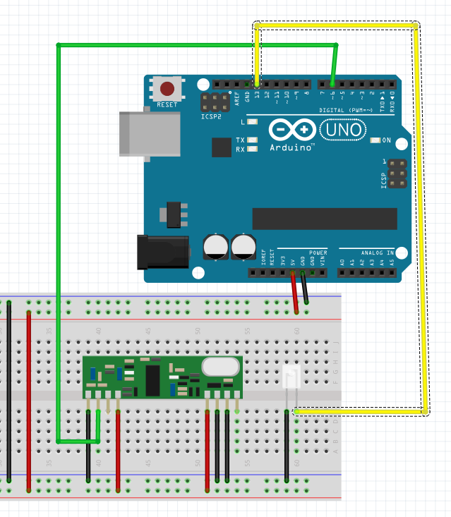
Receiver With IR LED To Turn Fire Place On
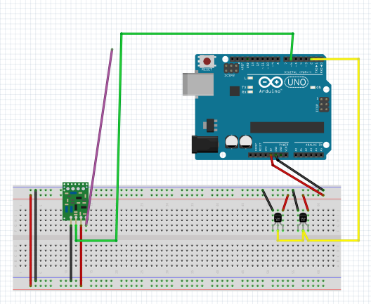
RF Transmitter With 2 One Wire Digital Temperature Sensor
Was it easier than buying heating elements for the cage? No it wasn’t, but it was a lot more fun and I learned a ton. With this action I became a Maker.
I put out the call goes to the readers of this article, go and make something amazing, repurpose a piece of furniture, It doesn’t have to be an electronic device, it can be anything. Use your imagination, take a risk and learn something new and become a Maker.

A new beginning
In everyone's life comes a time where they need, or want to change what they do. I have been working in the IT field as a manager/ System Admin/Programmer for so long (nearly 25 years) that it had become a comfortable jacket (you know the one with stains), but you love it and don't want to get rid of.
Hello Everybody
In everyone's life comes a time where they need, or want to change what they do. I have been working in the IT field as a manager/ System Admin/Programmer for so long (nearly 25 years) that it had become a comfortable jacket (you know the one with stains), but you love it and don't want to get rid of.
Suddenly I find myself in a position of not having a job and not being able to get one. If it's my age or just because the industry I loved had changed on me I am not sure.
After long consideration and some sleepless nights I have decided to put on a new jacket and see if I can reinvent myself. I want to see if I can combine my previous experience and my love and passion of creating things with the Arduino Micro-controller, and create myself a new jacket as The Arduino Maker Man. Helping you and others enjoy this world of the Arduino Micro-controller by making and creating wonderful things.

Find out about my online lessons at Curious.com by clicking om the icon below